We design and manufacture semiconductor chips, discrete power devices, and power modules for your products.
Less Energy
More Efficiency
  • Home
  • Products 
    • IPM
    • IGBT Modules
    • IGBT Discretes
    • IGBT Chips
    • SiC
    • FRD(MUR)
    • Bridge Rectifier
  • Application 
    • New Energy Vehicle
    • Home Appliance
    • Energy Storage
    • Industrial Equipment
    • Data Centers
  • Technology
  • Our Teams
  • Blog
  • Contact Us
  • …  
    • Home
    • Products 
      • IPM
      • IGBT Modules
      • IGBT Discretes
      • IGBT Chips
      • SiC
      • FRD(MUR)
      • Bridge Rectifier
    • Application 
      • New Energy Vehicle
      • Home Appliance
      • Energy Storage
      • Industrial Equipment
      • Data Centers
    • Technology
    • Our Teams
    • Blog
    • Contact Us
Sample Request
We design and manufacture semiconductor chips, discrete power devices, and power modules for your products.

How can four diodes "straighten out" alternating current? - Analysis of the working principle of the rectifier bridge

How can four diodes "straighten out" alternating current?

1.Introduction

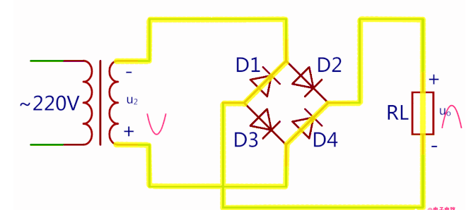
The single-phase rectifier bridge is composed of four ordinary diodes. It can convert alternating current (AC) into direct current (DC). For example, the mains power supply is 220V AC. Through a transformer, 220V AC can be converted to 15V AC, and then 15V AC is connected to the rectifier bridge. After passing through the rectifier bridge, it becomes 21V DC. Finally, it is stepped down and then supplied to the microcontroller system.

2.Working Principle

Section image

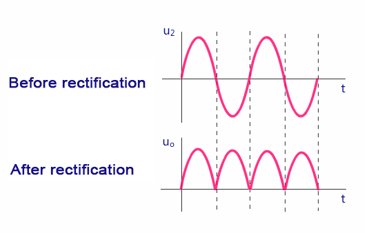
The specific conduction mode of the rectifier bridge is accomplished based on the unidirectional conduction principle of diodes. In simple terms, a diode conducts in the forward direction and is cut off in the reverse direction. That is to say, a diode only allows positive electricity to enter its positive pole and negative electricity to enter its negative pole. A diode only allows current to pass in one direction, so when it is connected to an AC circuit, it can make the current in the circuit flow only in one direction, enabling the load to receive pulsating direct current.

During each working cycle of the rectifier bridge, only two diodes are in operation at the same time. Therefore, we can divide the rectifier's working cycle into the positive half-cycle and the negative half-cycle.

a.Electrical circuit during the positive half-cycle

Electrical circuit during the positive half-cycle

b.Electrical circuit during the negative half-cycle

Section image

Filtering Capacitor

The voltage directly rectified by the rectifier bridge is not smooth enough and requires a filtering circuit to correct it. The function of the filtering circuit is to minimize the AC components in the pulsating DC voltage while retaining its DC component, thereby reducing the ripple coefficient of the output voltage and making the waveform more smooth, thus achieving a stable voltage.

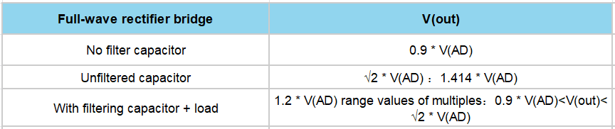
3. Output Voltage Value

Section image

4.Detection of Rectifier Bridge

Resistance Test:

The resistance test method utilizes the unidirectional conduction characteristic of the diode to determine whether it is good or bad by measuring the resistance value when it conducts in the forward direction and the absence of a reading when it is cut off in the reverse direction.

Voltage Drop Test:

The voltage drop test method is to directly test the diode chip inside the rectifier bridge using the diode function of the multimeter. The reading value is the reference value or approximate value of the voltage drop.

Section image

Measuring the Polarity of Each Pin of the Rectifier Bridge:

Set the multimeter to the R×1k range, connect the black probe to any pin of the bridge stack, and then measure the other three pins with the red probe. If the readings are all infinity, then the pin connected by the black probe is the positive output terminal of the bridge stack. If the reading is 4 to 10 kΩ, then the pin connected by the black probe is the negative output terminal of the bridge stack, and the other two pins are the AC input terminals of the bridge stack.

Subscribe
Previous
What is IGBT? A Comprehensive Guide to understanding...
Next
How to achieve technical matching between IGBT and MUR/FRD
 Return to site
Profile picture
Cancel
Cookie Use
We use cookies to improve browsing experience, security, and data collection. By accepting, you agree to the use of cookies for advertising and analytics. You can change your cookie settings at any time. Learn More
Accept all
Settings
Decline All
Cookie Settings
Necessary Cookies
These cookies enable core functionality such as security, network management, and accessibility. These cookies can’t be switched off.
Analytics Cookies
These cookies help us better understand how visitors interact with our website and help us discover errors.
Preferences Cookies
These cookies allow the website to remember choices you've made to provide enhanced functionality and personalization.
Save