

# PFC Circuits Explained: Why You Need One, How Boost PFC Works, and How to Choose
Introduction: When Certification Fails on Harmonics, Look at the Input Stage
Every power-electronics engineer has hit this: the design works, efficiency is fine - and the product stalls at IEC 61000-3-2 harmonic testing. Measure the input current and you see narrow, tall spikes with a power factor of 0.5-0.7. The problem is not your converter - it is the rectifier bridge and the bulk capacitor right at the front. Power Factor Correction (PFC) exists to fix exactly this, and this article explains it end to end.
The pain point: a poor power factor is not just a utility-bill issue - spike currents pollute the grid and disturb other equipment sharing the same line, which is why major markets write harmonic limits into mandatory standards.
---
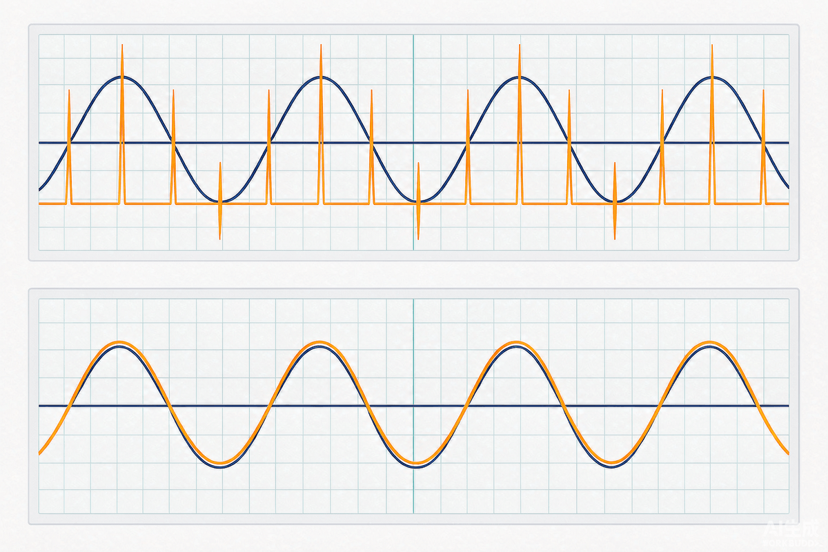
1. What Power Factor Actually Is: Displacement + Distortion
First, a loose definition needs fixing. Power factor is precisely PF = active power P / apparent power S - not "energy out divided by energy in". AC systems have three power types:
- Active power P - the part that does real work in the load;
- Reactive power Q - energy shuttling between source and inductance/capacitance without net work;
- Apparent power S - RMS voltage times RMS current; for sinusoids, S forms the power triangle with P and Q.
PF falls below 1 for two reasons: displacement - voltage and current out of phase (inductive or capacitive loads); and distortion - current waveform deviating from a sine (nonlinear loads, rich in harmonics). Displacement is easy: add a capacitor or inductor of suitable size. Distortion is the real challenge of every switch-mode power supply.
---
2. Why SMPS Input Current Is Spiky: Rectifier + Big Capacitor
A switch-mode supply input is a rectifier bridge feeding a bulk capacitor. The bridge diodes conduct only while the instantaneous AC voltage exceeds the capacitor voltage - so within each half-cycle (180 degrees), conduction occupies only a narrow angle near the peak (often just 30-70 degrees). To deliver rated power, the current is compressed into extremely narrow, high-amplitude charging spikes.
Three consequences: first, severe current distortion with high harmonic content, PF down to 0.5-0.7; second, the spikes create voltage drops across line impedance, distorting the grid voltage seen by everyone else; third, harmonics interfere with other equipment - the direct source of EMI/EMC issues. This is why standards such as IEC 61000-3-2 set harmonic limits for equipment above roughly 75W.
---
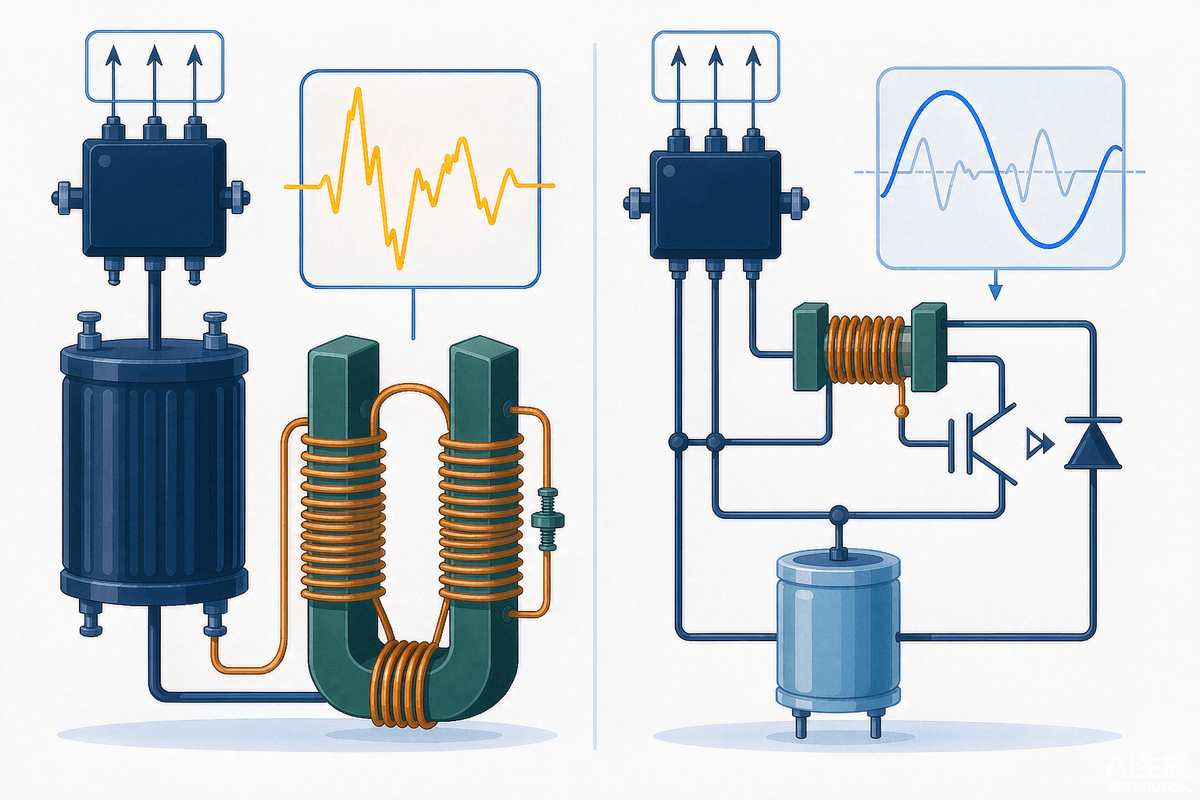
3. Passive vs Active PFC: The Trade-offs at a Glance
- Passive PFC: a line-frequency inductor between bridge and capacitor smooths the charging spikes. Simple, no control changes - but the inductor is big and heavy, PF typically reaches only 0.7-0.9, and filtering is limited. Best suited to retrofitting legacy products;
- Active PFC: a high-frequency switching stage (usually a Boost converter) after the bridge forces input current to follow the voltage waveform. PF reaches 0.99, small and light, harmonics handled thoroughly - at the cost of one more stage and control complexity.
In one sentence: new products use active PFC; passive remains only a low-cost retrofit trick.
---
4. Why Active PFC Must "Boost" Above 380V
This is the most overlooked piece of cleverness. The peak of a 220V AC line is about 311V, and with grid disturbances the instantaneous input can approach 380V. If the PFC output sat below the input peak, there would always be intervals where the input exceeds the output, the rectifier cuts off, current goes discontinuous - spikes return. Setting the Boost output at 380-400V (above the worst-case peak) lets the inductor keep drawing energy from the grid across the entire line cycle, shaping the input current into a continuous sinusoidal envelope. That is the whole answer to "why PFC is always a boost".
---
5. Three Operating Modes: CCM / DCM / CRM
- CCM (Continuous Conduction Mode): fixed switching frequency, duty cycle varies with instantaneous input, inductor current never reaches zero. Low stress, high PF - the choice for 250W-2000W designs;
- DCM (Discontinuous Conduction Mode): inductor current falls to zero within each cycle. Simple control, no diode reverse-recovery issue, but high current peaks - suitable below 250W;
- CRM/BCM (Critical/Boundary Conduction Mode): the next cycle starts exactly as inductor current reaches zero (zero-current switching). Cheap, easy to design, low turn-on loss - but frequency varies widely and the EMI filter needs careful design. The default for small and mid power.
A quick selection rule: power sets the mode, frequency sets the device. High-power CCM uses Si or SiC MOSFETs; small and mid power CRM uses dedicated controllers (BCM control ICs detect inductor zero-crossing on a ZCS pin to turn the switch on, with voltage and current sensing loops for regulation and limiting).
---
6. Going Further: Totem-Pole PFC and Wide-Bandgap (SiC / GaN)
A conventional bridge rectifier adds two fixed diode drops and caps efficiency. The totem-pole PFC replaces the bridge with a fast-switching leg plus a line-frequency leg, eliminating bridge loss - but the high-frequency leg must hard-switch or run in CRM. GaN HEMTs and SiC MOSFETs have no body-diode reverse recovery, which is exactly what turned totem-pole PFC from "theoretically better" into "the mainstream design". Today 1kW+ high-density supplies (fast chargers, server PSUs, OBC) widely use GaN totem-pole stages with efficiency above 98%.
Device requirements rise accordingly: gate driving, parasitic inductance control and thermal design of the fast leg all get stricter - which is where integrated drivers and advanced packaging pay off (driver-integrated SiC/GaN solutions significantly cut layout parasitics).
---
7. A Five-Point PFC Design Checklist
- Target power and efficiency budget - decides topology (CCM boost / CRM / totem-pole) and device technology (Si / SiC / GaN);
- Certification requirements - identify the applicable IEC 61000-3-2 class (A/C/D) and back-calculate the PF target;
- Boost output voltage - start at 380-400V, balancing downstream PWM-stage stress and ripple;
- EMI filter - variable-frequency CRM and totem-pole stages require filters covering the worst operating point;
- Protection and light load - overcurrent/overvoltage protection plus burst or skip-mode behavior at light load.
---
FAQ
Q1: Does a low power factor really cost money?
For households, essentially no - residential meters record active power only. Industrial users may face reactive-power or harmonic penalties, and the real costs are wasted current capacity, higher line losses, and oversized distribution infrastructure.
Q2: How big is the gap between passive and active PFC?
Passive designs typically reach PF 0.7-0.9 with bulky magnetics; active boost PFC reaches 0.98-0.99. Products that must pass harmonic certification (IEC 61000-3-2 Class D and similar) effectively require active PFC.
Q3: Why does PFC output 380-400V instead of 311V?
311V is only the peak of 220V AC. If the PFC output sat below the instantaneous input peak, the rectifier would cut off near the peaks and current would go discontinuous again. The output must exceed the worst-case input peak (about 380V) so current stays continuous and sinusoidal.
Q4: Which mode fits which power level?
Rule of thumb: below 250W use DCM/CRM (simple, cheap); 250W-2000W use CCM (lower stress, high PF); for the highest power or efficiency targets, use CCM totem-pole with SiC/GaN.
Q5: Why did totem-pole PFC only become popular recently?
The topology is old - the bottleneck was devices. The line-frequency leg can use ordinary MOSFETs or IGBTs, but the fast leg needs devices with no reverse recovery and very fast switching. Once SiC MOSFETs and GaN HEMTs matured, totem-pole PFC scaled to mass production.
---
Summary + CTA
The logic chain of PFC is simple once seen whole: rectifier + bulk capacitor → current spikes → harmonics and low PF → failed certification and a polluted grid → boost shaping the current into an in-phase sinusoid → output must exceed 380V → power level picks CCM/DCM/CRM → high-density designs move to totem-pole with GaN/SiC. Hold that chain and PFC stops being a black box.
Designing a high-density PFC or power stage that needs SiC MOSFETs, GaN devices or matching drivers? SHYSEMI offers wide-bandgap power devices and IPM solutions with local FAE support for topology selection and efficiency optimization. Browse the SHYSEMI product center or continue with our IGBT module selection guide.
---
