

# Common IGBT Modules Explained: Working Principle, Classification & Trench-Gate Design
Introduction: Know What You Are Buying Before You Size It
Many engineers select IGBT modules by voltage and current rating alone - only to discover mid-project that the "module" contains no gate driver or protection at all, or that its internal topology does not match the inverter bridge they drew. An IGBT module is not a "big discrete IGBT" - it is a power subsystem made of multiple die and an interconnect structure. Understanding its construction, physics and classification is the first step of a good selection.
The pain point: every parameter on the datasheet is true, but combining them wrongly costs you 3% of system efficiency, doubles your losses - or blows up the bridge. This article fixes the most common misconceptions in one pass.
---
1. What Is Actually Inside an IGBT Module
First, a widespread claim needs correcting - "an IGBT module contains IGBT die, antiparallel diodes, drive circuits and protection circuits". The second half is wrong: a standard industrial IGBT module contains only the power stage. Gate driving and protection live outside the module (only Intelligent Power Modules - IPMs - integrate driver plus overcurrent/overtemperature protection).
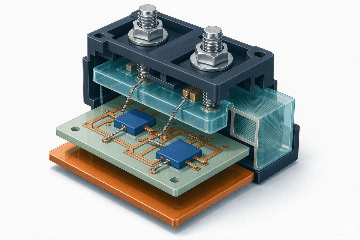
Inside a typical IGBT module you will find:
- IGBT die - one or several paralleled for higher current;
- Antiparallel freewheeling diodes (FWD) - one per IGBT, providing the inductive-load current path and absorbing reverse EMF;
- DBC ceramic substrate - electrical isolation plus thermal conduction between die and copper baseplate;
- Interconnects - aluminum wire bonds, or copper clip / silver-sinter joints in advanced packages;
- Gel and housing - silicone gel for moisture protection, the case and terminals defining the mounting style.
---
2. How an IGBT Actually Conducts: Conductivity Modulation
The popular explanation - "holes from the P region recombine with electrons from the N region, so current flows" - is not accurate. The real mechanism: when the gate-emitter voltage VGE exceeds the threshold, the P-body surface under the gate inverts and forms an N-type channel - exactly like a MOSFET.
The IGBT trick comes next: electrons flow through the channel into the N- drift region, while the P+ collector injects a large density of holes into the same region, raising its carrier concentration by orders of magnitude - conductivity modulation. That is how an IGBT keeps a low on-state voltage VCE(sat) at high voltage ratings, which a pure MOSFET cannot match - and why IGBTs dominate above 650V.
At turn-off the channel disappears, but the stored minority carriers must recombine, producing the tail current - the physical reason why IGBT turn-off loss is higher than SiC MOSFETs, and why SiC keeps taking over high-frequency applications.
---
3. Classification: Four Dimensions That Cover Every Module
Treating "standard / high-voltage / high-speed" as the classification is not enough - it is a loose parameter label. Four practical dimensions cover the market:
3.1 By internal topology
- Single switch (1-in-1): one IGBT + FWD, for choppers and PFC stages;
- Dual / half-bridge (2-in-1): upper and lower IGBTs in series with a midpoint output - note this is not "two IGBTs in antiparallel";
- Six-pack (6-in-1): complete three-phase inverter bridge - the workhorse of drives and VFDs;
- PIM / CIB: rectifier + brake chopper + inverter integrated in one package.
3.2 By voltage class
- 600/650V: home appliances, power tools, small servos;
- 1200V: industrial drives, EV traction, solar and storage - the mainstream;
- 1700V: rail auxiliary, mining, wind converters;
- 3300V and above: traction, HVDC, large STATCOMs.
3.3 By chip generation
From PT (punch-through) to NPT (non-punch-through) to Field-Stop trench-gate, each generation lowers turn-off loss and narrows the tail current at the same VCE(sat). Current-gen 1200V parts reach roughly 1.7V saturation voltage. One often-missed point: the IGBT and its FWD are co-designed - the diode reverse recovery directly drives switching loss and EMI.
3.4 By package
- 62mm / 34mm standards: solder-in workhorses of industrial drives;
- EconoDUAL, EasyPACK families: mid-power drives and automotive integration;
- Press-pack: HVDC and high-power traction;
- Discrete TO-247: low power and prototyping.
---
4. Six Advantages of High-Power Trench-Gate IGBT Modules
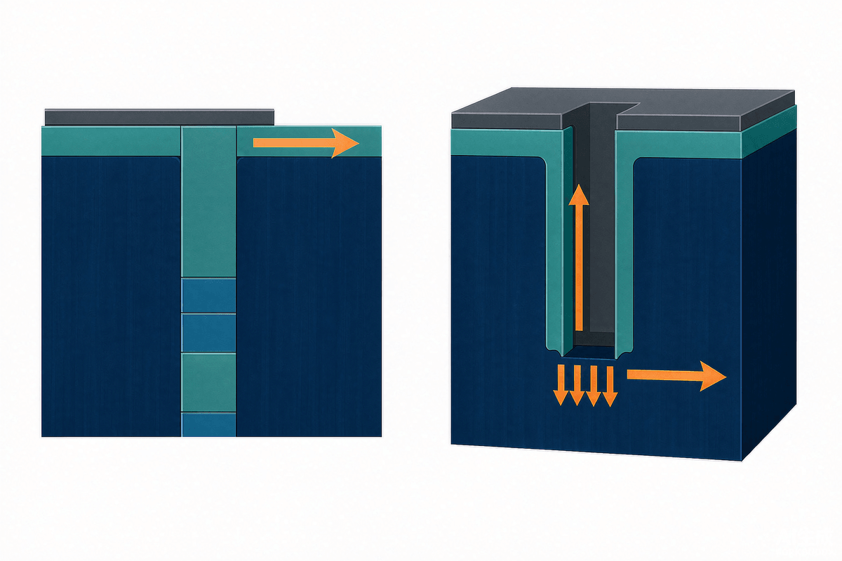
Trench-gate field-stop modules are the current mainstay of motor drives, VFDs and power conversion. Their advantages boil down to six:
- High voltage, high current: hundreds to thousands of volts and amps via multi-die paralleling and busbar sharing;
- High reliability: integrated FWDs, explosion-proof housing design, NTC temperature sensing - long life and fail-safe behavior;
- Low on-state voltage: trench + field-stop keeps VCE(sat) low, directly cutting conduction loss;
- Fast switching: higher cell density and lower gate charge push switching speed and frequency limits up;
- High integration: half-bridge / six-pack topologies on one DBC - compact and easy to mount;
- Reasonable cost: cheaper and far simpler to drive than GTO or IGCT at equal ratings.
One caveat: the faster switching that trench gates enable also means higher di/dt and dv/dt - your gate driver, gate resistor and busbar parasitics must keep up, or EMI and voltage spikes will eat the gains.
---
5. Five Questions to Answer Before Selecting
- What is the DC bus voltage, and how much margin? - sets the voltage class (typically 2-3x the operating voltage);
- Does the topology match? - count the switches inside: half-bridge, six-pack or PIM;
- What switching frequency? - decides how you trade VCE(sat) against Eoff (low frequency favors conduction, high frequency favors switching);
- What cooling is available? - Rth(j-c) and junction-temperature margin decide whether the module can run at full load long-term;
- Do you need short-circuit rating and NTC? - for high-reliability designs, prefer modules with SCC and temperature monitoring.
---
FAQ
Q1: Does an IGBT module include gate drive and protection?
No - standard industrial modules integrate only the power stage (IGBT die + FWD + substrate interconnect). Modules that integrate the driver plus overcurrent/overtemperature protection are IPMs - keep the two categories apart when selecting.
Q2: What does "bipolar IGBT module" mean?
The IGBT itself is a bipolar device - MOS gate control with bipolar conduction (hole-injection conductivity modulation). If a source means "two switches in one package", that is a dual / half-bridge module (series upper-lower arms), not "two IGBTs in antiparallel".
Q3: Why does an IGBT show a tail current at turn-off?
Conductivity modulation stores a large minority-carrier charge in the drift region; after the gate is discharged, those carriers must recombine, forming the tail current. Field-Stop technology thins the drift region to narrow the tail and cut turn-off loss.
Q4: Can a 1200V module be used on an 800V bus?
Not automatically. On 800V battery platforms, braking transients and inductive spikes can push instantaneous voltage close to or beyond 1200V - start with 1200V-class parts plus turn-off spike simulation, or move to 1700V.
Q5: IGBT module or SiC MOSFET module?
Below ~20kHz and cost-sensitive, IGBT still wins on value. Above ~50kHz, or when efficiency and volume matter (OBC, high-frequency power), SiC pulls ahead. Packages and drivers are not always interchangeable - do a system-level evaluation early.
---
Summary + CTA
Selecting an IGBT module means matching topology, voltage, frequency and cooling to the module's internal structure. Remember three sentences: modules contain only the power stage (drive and protection live outside); conduction relies on conductivity modulation (hence the tail current); classify by topology, voltage, chip generation and package.
Selecting IGBT or IPM modules for a drive, servo or power-conversion project? SHYSEMI offers a full 600V-1700V IGBT module, IPM and SiC portfolio with local FAE selection and reliability support. Browse the SHYSEMI product center or continue with our IPM package selection guide.
---
