

Introduction: 1,000 hours in the lab, three months in the field
“Dave, we ran HTGB on this part for a thousand hours. Parameters barely moved. So why did the customer’s unit blow up after three months?”
“You tested the gate oxide. It died at the solder joint.” Dave slid the report back. “Reliability isn’t one exam. It’s six. You sat one of them.”
This conversation happens in every power semiconductor FAE office, roughly weekly. The problem is rarely diligence — it is that “reliability testing” gets narrowed into “we burned it in for a while.” In reality it is a methodology for compressing years of field stress into months of lab time.
This article maps it out: what is actually being tested, why the tests are shaped the way they are, and where engineers most often fool themselves.
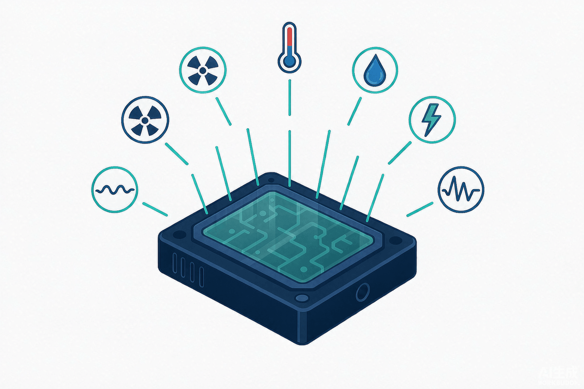
The one-line difference between parametric testing and reliability testing
Parametric testing answers “is it good right now?” Reliability testing answers “what is the probability it is still good in year five?” One is a snapshot; the other is a trend.
Parametric testReliability testWhat is measuredV(BR), VCE(sat), RDS(on), switching times, gate leakageThe same parameters, but with temperature, humidity, voltage, current and mechanical stress added over timeQuestion answeredDoes this part meet the datasheet today?How long will it last in the target application, and with what failure rate?Typical durationMilliseconds to minutes96 hours to 3,000 hours, sometimes morePass criteriaInside the datasheet windowDrift beyond 20% of initial value, or leakage beyond 2xWhat failure looks likeFails immediately, test stopsDrift first, accelerate next, fail last — the middle is where the information lives
That last row matters. The value of a reliability test is not the final pass/fail, it is the shape of the curve across dozens of read points. A flat line and a line that is flat then turns vertical may both “pass,” but the second one is a time bomb.
Why power devices age faster than logic chips
An MCU in a cabinet can run fifteen years. A power device in the same cabinet often fails at year five. Four physical reasons:
- It does the heavy lifting. Conduction loss becomes heat, and that heat must cross five interfaces — die, die attach, DBC, baseplate, heatsink. Every interface is a thermal resistance and a potential failure site.
- It flexes constantly. Silicon, solder, copper, ceramic and molding compound differ in CTE by three to ten times. Every power cycle is a micro-bend, and solder cracks are the accumulated result.
- It takes voltage and heat at the same time. Leakage rises with temperature; add high blocking voltage and a trace of surface ionic contamination is enough to erode breakdown margin.
- Its failure is energetic. Bus capacitance dumps its energy into a die a few millimeters square. The result is not a flag in a log — it is a rupture, a fire, a stopped line.
Six stress families: what reliability tests actually reproduce
Grouping tests by stress type is far more useful than memorizing standard numbers. Every test does the same thing: take a stress that occurs once every few years in the field and apply it densely over a few months.
StressRepresentative testTypical conditionsWhat it attacksTemperature + reverse biasHTRBTj_max (150/175°C), 80–100% rated V, 1,000 hJunction termination, passivation, surface ionsTemperature + gate biasHTGBTj_max, ±VGS(max), 1,000 hGate oxide (TDDB), threshold driftThermal cycling (ambient)TC-65 to +150°C, 500–1,000 cycles, transfer ≤1 minSolder, wire bonds, mold/frame interface (ΔTc fatigue)Thermal cycling (self-heating)IOL / power cyclingΔTj = 50–100 K, 5,000–15,000 cyclesSolder cracks, aluminum wire lift-off, die fractureHumidity + biasH3TRB / THB, HAST85°C/85%RH/1,000 h; 130°C/85%RH/96 hMoisture uptake, electrochemical migration, aluminum corrosionMechanicalShock, vibration, constant acceleration, lead strength1,500 G/0.5 ms; 20–2,000 Hz/20 G; 20,000 GInternal interconnects, leads, solder joints
Why 1,000 hours can stand in for 15 years
Two empirical models, both roughly fifty years old.
Arrhenius. Reaction rate rises exponentially with temperature: rate ∝ exp(−Ea/kT). For silicon devices with Ea ≈ 0.7 eV, that works out to failure rate doubling roughly every 10°C. A 1,000-hour run at 125°C is on the order of 8,000 hours at 85°C.
Coffin-Manson. Fatigue life ∝ (ΔT)^−n, with n ≈ 2 for solder fatigue. Double the temperature swing and life drops to a quarter. That is why power cycling at ΔTj = 100 K requires 5,000 cycles while ΔTj = 50 K requires 15,000 — the standard is not being lenient, it is following physics.
Both models have a precondition: the failure mechanism must not change. Push temperature too hard and solder fatigue turns into molding compound charring; change the mechanism and the extrapolation is worthless. Which is why acceleration has ceilings, and why a “1,000-hour pass” must be back-fitted to your actual temperature rise and swing — never used as a standalone conclusion.
Five traps that quietly invalidate a report
- Reading “pass” as “will not fail.” 77 samples with zero failures bounds the defect rate around 3% at 90% confidence. It does not prove zero. Batch uniformity and process control are a separate system.
- Cutting sample size to save cost. Ten or twenty parts collapses statistical confidence to near meaninglessness, and power device failures tend to be batch-related (same solder furnace, same wire bonder), which small samples miss entirely.
- Mismatching test conditions to the application. A 150°C-rated part in a 105°C cabinet extrapolated from 150°C data will overstate life. Conversely, frequent start-stop cycling produces ΔTj fatigue that ambient thermal cycling never reproduces.
- Testing the die and ignoring the package. Package-related mechanisms are frequently more than half of field failures, yet many “reliability reports” contain only HTRB and HTGB.
- No intermediate read points, no failure analysis. Measuring only at 0 h and 1,000 h throws away the degradation trajectory; skipping cross-sections and acoustic scans means you never learn what to fix.
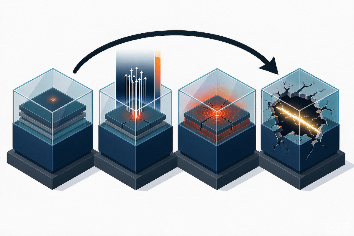
What skipping it actually costs
DimensionTypical consequenceOrder of magnitudeTechnicalInfant mortality (thin gate oxide, solder voids), parameter drift raising loss and temperature, thermal runaway from degraded RthBatch failures cluster 3–12 months after installationSafetyTraction inverter losing drive, charger short-circuit fire, PV DC arcing, industrial drive runawayOne incident can stop a line or trigger a recallEconomicField repair, batch recall, downtime, redesign and supply chain re-qualificationRecalls reach tens of millions of RMB; industrial downtime starts at tens of thousands per hourBrand & complianceNo AEC-Q101 means no automotive tier-1 access; CE/UL/CCC blocked; quality events amplify on social mediaReputation recovery is measured in years
FAQ
Is reliability testing the same as burn-in?
No. Burn-in is 100% screening — a short high-temperature bias to weed out infant mortality, aimed at outgoing quality. Reliability testing is sampled, long-duration, multi-stress evaluation aimed at proving the design and process lifetime capability. One is a sieve; the other is a medical report.
Is one qualification enough?
No. It is tied to a specific design + process + material set. Change the wafer fab, the solder alloy, the molding compound, the layout, even the wire diameter, and it needs re-evaluation. Automotive customers additionally require a formal PCN change-notification process.
How can a few dozen samples represent hundreds of thousands?
Through statistical sampling, not “representativeness.” With a homogeneous batch, 77 parts and zero failures supports “defect rate below ~3% at 90% confidence.” The precondition is homogeneity — which is why standards also mandate process control, lot traceability and 100% screening. Remove any of the three and the sampling conclusion collapses.
Why do parts still fail in the field after passing everything?
Three usual suspects: combined stresses the test matrix never reproduced (humidity plus high-frequency switching plus vibration); installation or thermal design that pushes real Tj far above the assumed value; and missing failure analysis, which misclassifies a batch problem as an isolated one.
Summary: reliability is designed in, not tested in
Back to that opening line — “you sat one of six exams” is the most expensive piece of common sense in this industry. Reliability lives in the die, the die attach, the wire bonds, the package, the thermal path, the gate drive and the protection. Any link left unverified means the system has no real margin.
For buyers and design engineers, judge a supplier on three things rather than on whether a report exists: which stress families it covers, whether sample size and lot data are transparent, and whether failures were analyzed and closed out.
