

Introduction: six acronyms everyone knows, half of them done wrong
“HTRB, HTGB, TC, H3TRB, HAST, IOL — all six are in my report. The customer still says coverage is insufficient. What does he actually want?”
“He doesn’t want the names,” Dave said. “He wants to know which part of the device each test attacks. You ran six tests, but TC only did 200 cycles and the IOL ΔTj was never calibrated. That’s six check-ups, three and a half of them real.”
The hard part of reliability testing was never knowing the list. It is knowing which mechanism each item targets, why the conditions are set that way, and why the pass criterion is that number. Once you have that, you can read anyone’s report and design your own matrix.
Here is each item, mechanism by mechanism, with a summary table you can use directly.
Two stress families: die-level and package-level
FamilyWhat it testsItemsWhere failures appearDie-level (electrical)Junction, oxide and passivation stability under high temperature and voltageHTRB, HTGBTermination, gate oxide, die surfacePackage-level (thermomechanical)Fatigue and delamination from CTE mismatchTC, IOLSolder, wire bonds, mold interfacesEnvironmentalMoisture, ions, corrosionH3TRB/THB, HASTMolding compound, lead frame, aluminumMechanicalShock, vibration, centrifugal loadShock, vibration, constant acceleration, lead integrityInterconnects, leads, solder joints
This split explains a common surprise: HTRB/HTGB and TC all pass, and the solder layer still cracks in the field. None of those three tested solder fatigue — that is IOL’s job.
HTRB: the junction and its surface
Heat the device to maximum junction temperature, apply 80–100% of rated blocking voltage across drain-source (or anode-cathode) with the gate shorted, and hold for 1,000 hours with periodic leakage reads.
It is hunting three things:
- Termination margin. High-voltage devices spread the field with field plates, guard rings and junction termination extensions. Field distribution shifts with temperature, and the weakest margin collapses first.
- Passivation and surface ions. Sodium and potassium drift under high temperature and field, altering surface charge and eroding breakdown voltage — the direct consequence of an unclean process.
- Long-term leakage stability. Going from 1 μA to 3 μA may still be in spec, but the trend is the message.
The usual criterion is leakage above 2× the initial value or an absolute limit. Because a relative 2× is sensitive for low-leakage parts, a proper report also states the absolute limit — otherwise 0.01 μA rising to 0.03 μA fails a perfectly good device.
HTGB: the gate oxide
HTGB applies the stress at the gate: Tj max, ±VGS(max), drain-source shorted, 1,000 hours. It attacks the gate oxide — the thinnest, most fragile layer in a power device, often only tens of nanometers thick.
The mechanism is TDDB (time-dependent dielectric breakdown): defects accumulate under constant field until a critical point, then the oxide conducts and the gate is lost. The rate is extremely sensitive to temperature, oxide quality, interface state density and any history of gate overvoltage.
- Igss — the most direct indicator, typically failed at 2× initial value.
- Vth drift — reflects trapped charge in the oxide and at the interface.
- Subtle shifts in transconductance and on-resistance — early signs of localized damage.
One frequently skipped detail: negative bias matters too. Positive bias stresses the channel-side oxide; negative bias stresses the opposite interface and its traps. The failure modes differ, and testing only one polarity covers half the risk.
Temperature cycling: fatigue from expansion and contraction
TC swings the part between -55 and +150°C (or -65 to +150°C) for 1,000 cycles, with dwell times long enough for the whole package to reach equilibrium (typically ≥10 minutes) and a controlled transfer time (usually ≤1 minute).
It does not test the die. It tests interfaces. Silicon (CTE ≈ 2.6 ppm/K), solder (≈20–25), copper (≈17), alumina (≈7) and molding compound (≈10–20) are bonded together, so every cycle pulls them against each other.
Failure typically progresses: micro-cracks at the solder fillet edge → propagation inward → local thermal resistance rises → junction temperature climbs → faster propagation. Wire-bond heel fatigue and mold/frame delamination often accompany it.
One parameter decides severity: transfer time. Slow transfer means small internal gradients and milder stress; fast transfer creates a transient differential between die and case and concentrates stress. Two “1,000-cycle” reports with different transfer times can differ by a factor of two in severity — which is why a report without transfer time is not comparable.
H3TRB: moisture and ions
H3TRB (also called THB, or 85/85) runs 85°C, 85% RH with 80% rated bias for 1,000 hours. It reproduces tropical, outdoor and humid-room environments.
Moisture inside a package does three things:
- Lowers insulation resistance. Polarized water molecules reduce surface and bulk resistance, and leakage climbs.
- Drives electrochemical migration. Bias plus moisture plus ions (from flux, molding compound, environment) dissolves metal at the anode and plates it at the cathode, growing dendrites until a short forms.
- Corrodes aluminum. With halide ions and moisture, aluminum metallization pits, raising on-resistance and eventually opening.
Criteria include leakage, parameter drift and visual inspection. Some failures are invisible electrically until a cross-section reveals dendrites — which is why a credible report includes failure analysis rather than a bare “pass.”
HAST: compressing 1,000 hours into 96
HAST accelerates H3TRB: parts go into a pressure vessel at 130°C/85% RH (unsaturated steam) under bias for 96 hours. Higher temperature and higher water-vapour pressure accelerate both ingress and electrochemistry.
Three boundaries, and crossing any of them invalidates the result:
- The mechanism must not change. Push temperature too far and the molding compound softens or degrades; the failure becomes thermal damage, not moisture corrosion, and 96 hours no longer extrapolates to 1,000.
- Only non-hermetic packages. Hermetic ceramic or metal parts do not absorb moisture; HAST is wasted on them.
- It is a screen. 96 hours catches poor sealing and contaminated interfaces quickly, but lifetime extrapolation still needs THB or longer data.
Practical pattern: HAST for fast iteration during development (results in a week), THB for the formal qualification conclusion. Running both costs little and changes what the report is worth.
IOL power cycling: solder and wire bonds
IOL differs from the previous five in one fundamental way: the heat is generated inside the device, not applied from outside.
Power pulses heat the die to a set ΔTj (commonly 50, 70 or 100 K), then the device cools, for thousands of cycles. Because heat originates in the die, the gradient between die and solder is steep — exactly like real operation.
ParameterMeaningWhy it mattersΔTjJunction temperature swingSets fatigue life: life ∝ (ΔTj)^-n, n ≈ 2Δt / cycleHeat and cool durationAffects gradient and creep fraction; short cycles are harsherTj,max / Tj,minAbsolute temperature levelHigher mean temperature accelerates creep, shortening life at the same ΔTjCycle count5,000–15,000 depending on ΔTjMust be read together with ΔTj, never alone
Criteria are typically VCE(sat) or RDS(on) up 20%, or Rth up 20%. Why not wait until it dies? Because power device failure is gradual: solder cracks raise Rth, higher Rth raises Tj, higher Tj accelerates cracking. The 20% line separates “still usable” from “about to run away,” and leaves engineering margin.
One detail worth knowing: how junction temperature is measured. VCE(sat) or the body-diode drop serves as a temperature-sensitive parameter (TSP), calibrated at low current, then sampled between power pulses. If the calibration is wrong, ΔTj is fiction and the whole test is worthless.
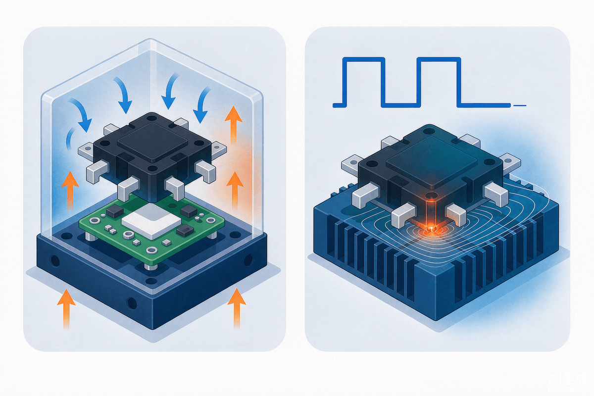
This is also where TC and IOL get confused: TC swing is ΔTc (case or ambient), IOL swing is ΔTj (junction). For the same 100 K, the damage is not remotely comparable — the junction case has a much steeper gradient and higher interfacial stress.
Mechanical testing: not just a shipping check
- Mechanical shock: typically 1,500 G, 0.5 ms half-sine, simulating drop and impact. Targets internal interconnects and lead roots.
- Variable-frequency vibration: 20–2,000 Hz at 20 G peak, swept to find resonances. Long wire bonds and large packages amplify at certain frequencies and break.
- Constant acceleration: typically 20,000 G for centrifugal and high-g environments such as rotating equipment.
- Lead integrity: bend and pull tests on package forming quality and lead material.
These are often treated as paperwork until a unit “doesn’t work installed, works on the bench” — usually a wire bond making intermittent contact under vibration, exactly what mechanical testing exists to catch.
The whole matrix in one table
ItemDominant stressMain failure modeTypical criterionHTRBHigh temperature + reverse biasBreakdown drift, leakage rise, surface ion driftLeakage >2× initial or beyond absolute limitHTGBHigh temperature + gate biasGate oxide TDDB, Vth shift, Igss riseIgss >2× initial, Vth out of specTCAmbient thermal cyclingSolder cracks, wire fatigue, delaminationParameter drift, delamination or cracks on scanH3TRB / THBHumidity + biasElectrochemical migration, Al corrosion, insulation lossLeakage rise, drift, visual or cross-section findingsHASTPressurized humidity + biasSeal defects, rapid moisture ingressSame as H3TRB, judged at 96 hIOL / PCSelf-heating ΔTj cyclingSolder fatigue, Al wire lift-off, die crackVCE(sat)/RDS(on) +20%, Rth +20%MechanicalShock, vibration, accelerationWire break, lead crack, joint fatigueElectrical anomaly, X-ray or cross-section defects
FAQ
What is the actual difference between HTRB and HTGB?
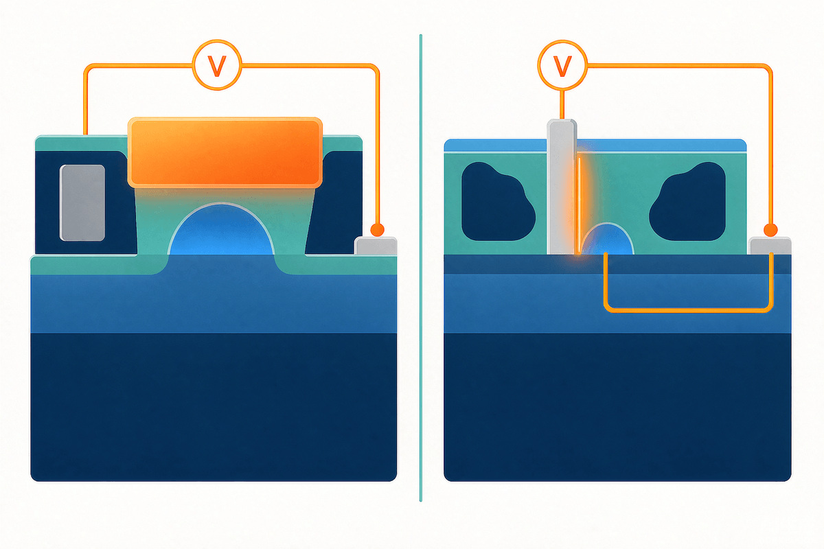
Where the stress is applied. HTRB puts high voltage across drain-source (or anode-cathode) with the gate shorted, testing junction and termination breakdown stability plus surface ions. HTGB puts voltage across gate-source with drain-source shorted, testing gate oxide TDDB and threshold drift. One attacks the body, the other the gate.
How is temperature cycling different from power cycling?
The heat source. TC uses a chamber, so the swing is ΔTc at the case and the package heats uniformly. IOL self-heats the die, so the swing is ΔTj with a steep gradient between die and solder. For the same 100 K, IOL damages the solder far more.
Why is the IOL criterion a 20% parameter shift rather than outright failure?
Because failure is gradual. Cracks raise Rth, Rth raises Tj, Tj accelerates cracking — by the time it opens, the original cause is unrecoverable. The 20% line separates still-usable from about-to-run-away and preserves margin.
Is 96 hours of HAST really equivalent to 1,000 hours of THB?
Under specific preconditions: non-hermetic package, unchanged failure mechanism (moisture-driven corrosion and migration), and no material degradation from the acceleration itself. Change the mechanism and they are not interchangeable, which is why a proper report states the acceleration model and assumptions.
