

Executive Summary
- FO Pin Definition: The Fault Output (FO) pin serves as a diagnostic interface that notifies external controllers when internal protection functions are triggered. Simultaneously, it disables all low-side IGBT phases to ensure hardware self-protection.
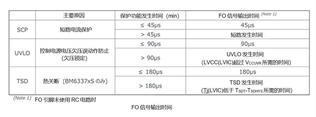
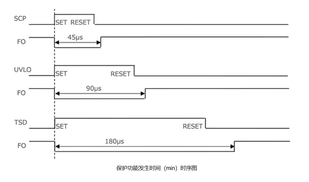
- Pulse Width Identification: The duration of the low-level FO signal varies depending on the specific protection mechanism triggered. This unique feature of this series allows systems to identify the fault type (e.g., SCP vs. UVLO) via pulse-width analysis.
- Integrated Input Capability: The FO pin functions as a bidirectional I/O. By integrating an external RC circuit, developers can adjust the time constant to extend the shutdown duration of the low-side IGBTs.
- Signal Integrity for Isolated Systems: In designs where FO signals are transmitted to an MCU via optocouplers or other isolation devices, the RC input function can be utilized to extend the FO pulse. This ensures the signal exceeds the isolation transmission delay (e.g., 45µs for SCP), guaranteeing reliable detection by the MCU.

1. Overview
The Fault Output (FO) function of the Intelligent Power Module (IPM) acts as the primary alarm interface for the integrated protection system. Its core objective is to rapidly deactivate power devices upon fault detection and transmit a status signal to the external MCU or controller to initiate system-level protection.
This technical note focuses on the Fault Output (FO) function, the fifth installment in our "Protection Functions and Operational Timing" series. The comprehensive IPM protection suite includes:
- Short-Circuit Protection (SCP)
- Control Power Under-Voltage Lockout (UVLO)
- Thermal Shutdown (TSD)
- Analog Temperature Output (VOT)
- Fault Output (FO)
- Control Inputs (HINU/V/W, LINU/V/W)

2. Functional Mechanism of the FO Pin
The FO pin communicates the activation of internal protection logic to external systems while forcing a shutdown of the low-side IGBTs to prevent module damage.
The Low-side Gate Drive (LVIC) within this IGBT IPM series integrates protection features such as SCP and UVLO. When any of these protections are triggered, the FO pin transitions from a High (H) state to a Low (L) state.
The FO pin utilizes a bidirectional I/O structure:
- Output: Open-drain configuration.
- Input: Schmitt-trigger buffer input.

The internal logic monitors the voltage level at the FO pin; if a Low level is detected, all low-side IGBTs are forcibly deactivated. Furthermore, external RC components allow for the customization of this shutdown interval.
3. HVIC vs. FO Correlation
The High-side Gate Drive (HVIC) also features UVLO protection; however, this is independent of the FO output. Consequently, an HVIC UVLO event will not trigger a change in the FO pin state.
For further details, please refer to the specific documentation on Control Power Under-Voltage Lockout (UVLO).
4. Output Characteristics and Diagnostic Logic
When LVIC protection is activated, the FO pin pulls Low to alert the system. This allows the MCU to recognize the IPM’s protected state, execute safety protocols, and log the fault.
As illustrated in the timing diagrams, the duration of the FO Low signal is determined by the specific fault type. This proprietary feature enables precise fault diagnosis—measuring the pulse width allows the system to differentiate between various protection triggers. If the underlying fault persists beyond the programmed FO output time, the pin will remain Low until the condition is cleared.
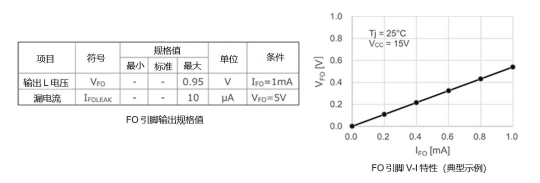
Electrical Specifications:
As an open-drain output, the FO pin requires an external pull-up resistor. The Absolute Maximum Ratings are:
- Applied Voltage ($V_{FO}$): -0.5V to $V_{CC}$ + 0.5V (relative to FO-GND)
- Sink Current ($I_{FO}$): 1mA
Designers must select pull-up voltages and resistances within these limits. For a 5V logic system, a 10kΩ resistor is recommended. This provides a 50% safety margin for sink current and ensures minimal voltage drop due to leakage current ($5V - 10k\Omega \times 10\mu A = 4.9V$), maintaining full compatibility with 5V CMOS/TTL logic levels.
5. Input Functionality and Signal Extension
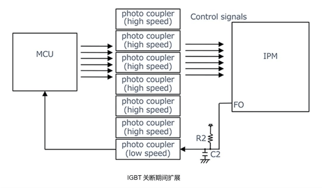
Because the FO pin is internally linked to the low-side IGBT gate control, it can be driven externally. By adding a resistor (R_2) and capacitor (C_2) to the FO line, the charging time of C_2can be tuned to extend the low-side IGBT "Off" duration.
This is particularly critical when using opto-isolation. If the isolation stage introduces a propagation delay longer than the minimum FO pulse (e.g., the 45µs SCP pulse), the MCU might fail to capture the fault. The RC network extends the FO signal duration to ensure the MCU reliably registers the event.
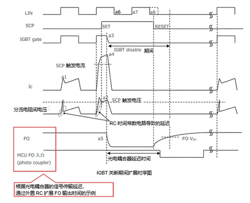
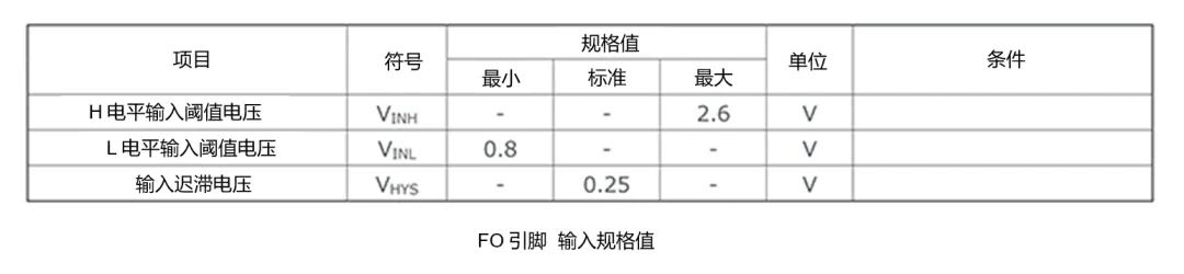
Note: The RC time constant must be calculated based on the FO pin’s input threshold and hysteresis voltages.
Technical Support We recognize that implementing advanced power modules involves complex design considerations. If you require further clarification on timing characteristics or specific product data, please contact our technical department. We will be happy to arrange a consultation with a field applications engineer to assist with your design.
Would you like me to provide a sample calculation for the RC time constant required to achieve a specific FO pulse extension?