

In power electronics systems, thermal protection for high-power IGBT (Insulated Gate Bipolar Transistor) modules is absolutely critical. To achieve precise temperature monitoring, SHYSEMI (Shenhuaying Semiconductor) integrates NTC temperature sensors across its entire lineup of high-performance IGBT modules.
What is an NTC Thermistor?
NTC stands for Negative Temperature Coefficient. The defining characteristic of an NTC thermistor is that its electrical resistance decreases exponentially as the temperature rises.

NTC Applications in IGBT Modules
During high-power operation, IGBT chips generate substantial Joule heating. SHYSEMI integrates the NTC thermistor directly onto the IGBT substrate or in close proximity to the chips to monitor internal junction or case temperatures in real time.
By accurately measuring the change in NTC resistance, the gate drive control system can track dynamic temperature shifts instantly. This enables:
- Thermal Protection: Triggering derating operation or shutdown protection when temperatures exceed safe thresholds.
- Optimized Thermal Management: Dynamically adjusting cooling fan speeds or liquid coolant flow rates to improve overall system efficiency and lifespan.
Resistance and Temperature Measurement Techniques
There are two primary methods used to measure the temperature of an IGBT module's NTC sensor: analog circuit measurement and digital measurement.
1. Analog Circuit Measurement
The most fundamental analog method relies on a voltage divider network configured as a thermal sensing circuit.
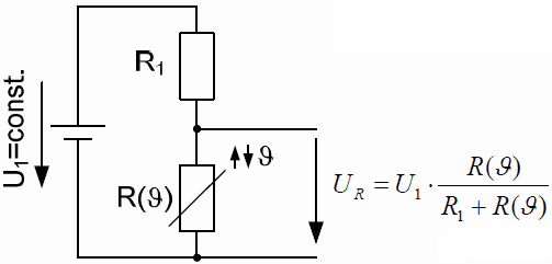
Data sheets typically present NTC characteristics in two formats. The first is a graphical approach where resistance is a function of temperature: R=f(θ). This curve can be mathematically approximated using standard exponential equations to describe all parameters.
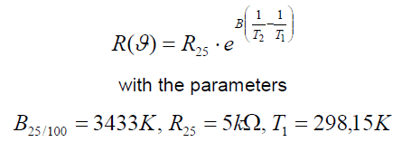
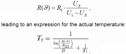
For higher precision within narrower temperature ranges, data sheets also provide specific B25/50 and B25/80 values. Based on the measured voltage UR, the actual resistance Rf(θ) can be calculated. A microprocessor can easily evaluate this equation using the digitized UR as an input to find the expected temperature.
Note: If you only need a maximum temperature limit as a threshold signal, a simple comparator circuit triggered by a predefined voltage value is sufficient.
Selecting the Divider Resistor (R1)
Choosing R1 requires careful optimization to ensure accurate readings:
- If R1 is too small, excessive current flows through the NTC. This causes self-heating, which skews the measurement results.
- If R1 is too large, the measured voltage drop becomes too small, reducing measurement resolution and accuracy.
To minimize self-heating effects, thermal analysis is highly useful. The NTC has a thermal conductivity of 145 K/W. If a 1 K temperature error is acceptable, the internal power dissipation of the NTC must not exceed Pmax = 6.9 mW.
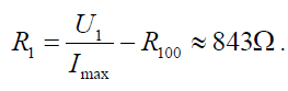
Assuming a maximum measurement temperature of 100°C, the NTC resistance drops to R100 = 493 Omega. The maximum allowable current can be calculated from this value. For a supply voltage of U1 = 5 V and a target current limit of 3 mA, the calculated resistor value for R1 would be approximately 1.17 k Omega.
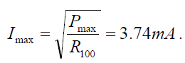
Since that is not a standard resistor value, a 910 Omega resistor can be selected, resulting in Imax = 3.56 mA. As long as a 1 K variance is acceptable, any value that limits the current to under 4 mA is appropriate.
2. Digital Measurement
Instead of using a standard voltage divider, this method utilizes the NTC's temperature-dependent resistance to modify the time constant of an RC network.
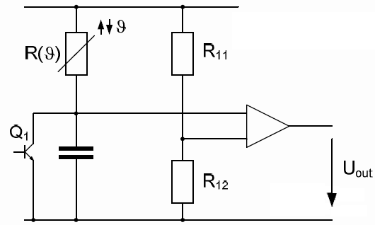
In this setup, resistors R11 and R12 define the threshold at which a comparator switches its output state. The output signal voltage Uout is then used to drive a transistor (Q1) to discharge a capacitor. The capacitor charges back up through the NTC resistor Rf(θ), forcing Uout to operate in a pulsed mode with a frequency defined by fout = g(θ).
To determine the actual temperature from Uout, the system simply counts the pulses within a defined time frame. This pulse count maps directly to a temperature value. Engineers can resolve this mapping using analytical equations or a lookup table with linear interpolation between the two closest calibration points.
Software Implementation: For actual software algorithms, SHYSEMI recommends either direct calculation via analytical equations or implementing a "pulse count to temperature" lookup table with linear interpolation inside the microcontroller. This approach ensures highly efficient and highly accurate real-time temperature readings for the IGBT module.
Does Adding an NTC Increase the Cost of the IGBT Module?
No. To ensure more accurate temperature tracking under varying environmental conditions, provide faster thermal feedback, and enhance operating stability, SHYSEMI includes integrated NTC sensors in its IGBT modules at no additional cost.

For specific model details or to request a quote, please contact us via email: info@shysemi.com! Or add us on WhatsApp: +86 15361554542