

In power electronics design, the IGBT gate driver architecture directly impacts overall system performance, thermal behavior, and operational reliability. Among various isolation topologies, pulse transformer isolated gate drivers are widely adopted across industrial applications due to their high reliability, cost-effectiveness, and robust immunity to electromagnetic interference (EMI).
This article explores the fundamental operating principles of pulse transformer gate drives, evaluates three primary implementation topologies, and analyzes their key application scenarios.

Operating Principle of Pulse Transformer Isolated IGBT Gate Drives
Pulse transformer isolation transfers gate control signals via magnetic coupling, establishing galvanically isolated domains between the low-voltage control circuitry and the high-voltage power stage. The core signal flow operates as follows:
- Signal Transmission Mechanism: Pulse-Width Modulation (PWM) signals generated by the controller drive the primary winding of the transformer, coupling energy magnetically across the core to the secondary winding.
- Galvanic Isolation: The core material and winding insulation provide high-voltage galvanic isolation—typically rated for several kilovolts (kV)—protecting sensitive controller ICs from high dV/dt noise.
- Signal Conditioning: The induced AC voltage on the secondary winding passes through signal conditioning circuitry before driving the IGBT gate-emitter (VGE) junction.
Engineering Insight from SHYSEMI: Because this driving approach eliminates the need for independent isolated power supplies on the secondary side, it significantly simplifies system topology, making it an ideal choice for low-to-medium frequency switching applications.
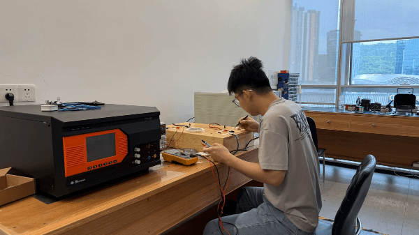
SHYSEMI's engineer Jack
3 Core Topologies for Pulse Transformer Isolated Gate Drives
Power electronics engineers typically utilize three structural methods to implement pulse transformer gate drivers:
1. Passive Drive Method
In a passive topology, the transformer’s secondary output directly drives the IGBT gate terminals (VGE).
- Pros: Highly simplified circuit structure requiring no auxiliary secondary power supply.
- Cons: High internal gate-emitter capacitance (CIES / CGE) in modern IGBTs can cause severe gate voltage waveform distortion. Preventing this typically requires high-power input driving signals on the primary side.
2. Active Drive Method
In an active topology, the pulse transformer serves solely as an isolated signal path. The secondary side incorporates active signal-shaping and amplification circuitry to drive the IGBT gate.
- Pros: Delivers crisp, high-quality gate drive waveforms with sharp rise and fall times.
- Cons: Requires an additional isolated auxiliary power supply to feed the secondary-side amplifier. Improperly designed auxiliary power stages can introduce parasitic capacitive coupling and EMI vulnerabilities.
3. Self-Powered Drive Method
This approach uses high-frequency carrier modulation (typically above a few MHz) overlaid on the PWM control signal at the primary winding.
- Secondary Action: The high-frequency carrier is rectified on the secondary side to generate a local self-powered auxiliary rail, while the original PWM gate signal is recovered via a demodulation circuit.
- Trade-offs: While it solves the isolated bias supply requirement, it adds significant circuit complexity and component cost.
Key Advantages of Pulse Transformer Isolated Gate Drives
High Reliability & Noise Immunity: Magnetic isolation inherently blocks high common-mode transients (dV/dt), making it exceptionally durable in harsh industrial noise environments.
- Fast Transient Response: Provides nanosecond-level propagation delay, meeting the high-frequency switching requirements of modern Switch-Mode Power Supplies (SMPS).
- Cost Efficiency: Eliminates expensive optocouplers or isolated gate driver ICs, reducing the total Bill of Materials (BOM).
- Compact Footprint: Simple components minimize PCB space requirements, streamlining layout and manufacturability.

Actual photos of Shysemi's production line
Key Applications of SHYSEMI Pulse Transformer Gate Drives
Leveraging years of power semiconductor expertise, SHYSEMI highlights the primary application sectors for pulse transformer gate drive topologies:
1. Industrial Motor Drives
In Variable Frequency Drives (VFDs) and AC servo drives, pulse transformer isolation provides robust voltage decoupling. SHYSEMI field-proven solutions demonstrate superior performance in multi-axis motor control systems where multiple isolated gate drives are required.
In photovoltaic (PV) inverters and wind power converters, optimized SHYSEMI pulse transformer designs ensure stable, long-term operation under elevated temperatures and high humidity, while optimizing overall system cost.
Medium-to-high-power UPS topologies rely on driving multiple parallel IGBT modules. SHYSEMI offers specialized gate drive modules for UPS architectures, delivering high power density and reliable power continuity.
4. Induction Heating Equipment
Pulse transformer architectures excel in high-frequency switching power supplies due to their high power density and strong suppression of parasitic electromagnetic interference.

Conclusion
Designing a pulse transformer gate drive circuit is rarely a one-size-fits-all process; engineers must carefully balance switching frequencies, duty cycle variations, and gate charge (Qg) requirements. Each of the three topologies discussed above offers distinct trade-offs in complexity, cost, and waveform integrity.
For tailored technical support, custom driver module selections, or design inquiries, contact the SHYSEMI engineering team today.