

Table of Contents:
- IPM Short-Circuit Protection Principle
- Components of Short-Circuit Time (Tsc)
- Case Study
Key Takeaways
RC filter, single resistor sampling circuit, sampling signal, IGBT drive, IPM design, overcompensation phenomenon, filter circuit
Intelligent Power Modules (IPMs) feature built-in monitoring and protection mechanisms, greatly simplifying user applications.
Among these, short-circuit protection is one of the core safety functions.IPMs utilize short-circuit-tolerant IGBTs as power control switches and integrate dedicated overcurrent protection circuitry. This circuit monitors overcurrent and short-circuit events through the ITRIP pin. Upon detecting an anomaly, it triggers a fault signal and instantly shuts down all six IGBTs.
This design simplifies the customer’s circuit layout while ensuring high system reliability. The following section briefly outlines how to properly implement short-circuit protection in IPM design.

Components of short-circuit time (Tsc) include the following major factors:
1.Time constant of the external RC filter
2.Driver delay within the IPM
3.Sampling circuit delay
Time constant of the external RC filter: RC filters are often used to smooth circuit signals, but they also introduce a certain delay. The time constant is expressed as τ = R × C, where R is the resistance and C is the capacitance. In design, a balance must be struck between filtering effectiveness and response speed to ensure that this delay does not compromise protection timeliness.
Driver delay within the IPM: After receiving a signal from the control circuit, the internal gate drive circuit requires a certain time to fully turn the IGBT on or off. This delay also contributes to Tsc, and the exact value should be referenced from the IPM datasheet.
Sampling circuit delay: In common applications such as household appliances, single-resistor sampling circuits are widely used, typically in combination with an RC-type low-pass filter to effectively suppress high-frequency noise on the sampling resistor.
The following shows an example circuit using a single-resistor sampling method.

The sampled signal may be distorted due to the leakage inductance of the wiring itself and the resistor. Considering this, let's assume we use the sampling resistor solution shown in the figure below:

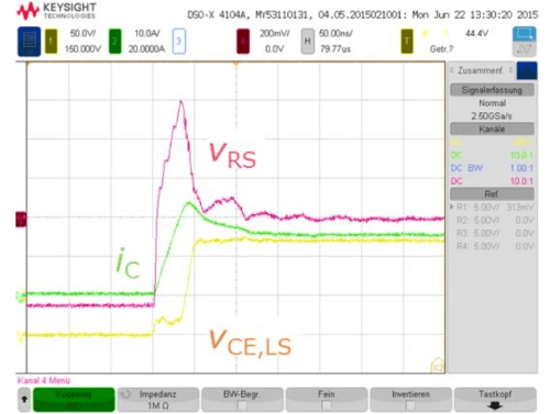
Under ambient conditions of T = 25℃, VDC = 125 V, and di/dt = 590 A/µs, the measured waveform is shown below.

The test results indicate that the induced voltage Uind is 7 V.
Based on this, the leakage inductance Lshsub> is calculated as 7 V divided by (590 A/µs), yielding Lsh ≈ 11.9 nH.
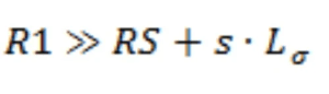
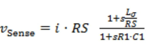
we can obtain:
Clearly, the filtering effect is optimal when the following equation holds.
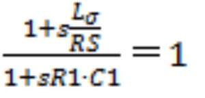
Thus, we can obtain:
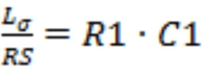
Substituting the previously obtained parameters into the calculation: leakage inductance Ls = 11.9 nH, sampling resistor Rₛ = 30 mΩ, and R1 = 100 Ω, we calculate that C1 = 3.966 nF.
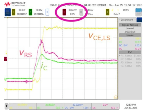
However, for practical reasons, we decided to use a slightly smaller capacitor value, namely 3.3 nF. Actual testing shows that using a 100 ohm resistor and a 3.3 nF capacitor results in slight overcompensation:
After fine-tuning, using 470 Ω and 680 pF yielded better results:
Thus, the calculated time constant of the external RC filter is 0.32 microseconds. However, in practical applications, to ensure stability and compatibility with different device parameters, it is generally recommended to set the time constant to around 1ms, and preferably no more than 2ms, as a safety margin.
The filter circuit time constant is the sum of the two-stage time constants: (100 Ω x 1 nF) + (1.8 kΩ x 1 nF) = 1.9 µs.
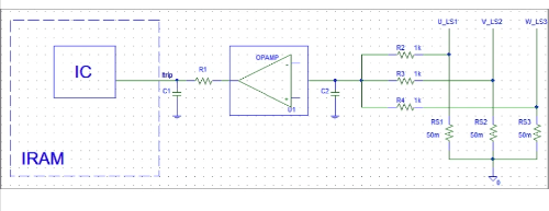
When designing an overcurrent protection circuit that includes a comparator (see the example below), careful selection of RC parameters is crucial. The time constant of the entire filter must account for not only the two-stage RC network but also the response time of the comparator itself.
Summary
In summary, careful planning of filter circuit parameters is essential when designing an IPM short-circuit protection system. The combined delay from the filter circuit and comparator response time must fall within the total short-circuit protection response time (Tsc).
To ensure system safety and reliability, Tsc must always remain shorter than the maximum short-circuit duration tolerated by the IPM.