

In the field of power electronics, the insulated-gate bipolar transistor (IGBT) is undoubtedly a core device for modern energy conversion and control. It cleverly combines the advantages of the high input impedance of a MOSFET with the low on-state voltage drop of a BJT. Analyzing its equivalent circuit is a key step to a thorough understanding of the operating characteristics and dynamic behavior of an IGBT. SHYSEMI will comprehensively explain the equivalent circuit model of the IGBT, covering both IGBT discrete and IGBT modules, and explore its significance in practical applications.
1.Why is anIGBT equivalent circuitnecessary?
In actual circuit design and analysis, complex physical models are not always feasible. Equivalent circuits simulate the electrical characteristics of IGBTs using basic circuit elements (such as resistors, capacitors, voltage sources, and current sources), providing engineers with the following benefits:
- Simulation Analysis: Perform system-level simulations in software such as PSPICE and LTspice to predict circuit behavior.
- Performance Prediction: Evaluate key parameters such as switching loss, conduction loss, and reverse recovery characteristics. Fault Diagnosis: Understand device performance under abnormal operating conditions such as overvoltage, overcurrent, and short circuit.
- Application Optimization: Provides a theoretical basis for driver circuit design, snubber circuit design, and heat dissipation design.
2.Equivalent Circuit Model of a Single IGBT
An IGBT is an independent device, and its equivalent circuit model can be divided into static and dynamic models.
2.1 Static Equivalent Circuit (On-State Model)
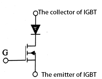
When the IGBT is in the stable on-state, its model can be simplified to a Darlington structure with a MOSFET driving a PNP-type BJT.
The input section exhibits capacitive characteristics, equivalent to a gate-emitter capacitance Cge.
The output section can be equivalent to a series connection of a constant voltage source (representing the threshold voltage Vce(sat)) and a resistor (representing the on-resistance Ron).
This simple model facilitates quick calculation of the on-state voltage drop and conduction loss.
2.2 Dynamic Switching Equivalent Circuit
The dynamic model is central to understanding the IGBT switching process (turn-on and turn-off), introducing inter-electrode capacitance and carrier storage effects.
Key Capacitors:
- Gate-Emitter Capacitance (Cge)
- Gate-Collector Capacitance (Cgc) or Miller Capacitance
- Collector-Emitter Capacitance (Cce)

Equivalent Circuit: The dynamic model can be viewed as a voltage-controlled current source, whose output current is controlled by the gate voltage Vge and control logic, and is strongly influenced by the three inter-electrode capacitances. Miller capacitance Cgc plays a crucial role in the switching process and is the root cause of the Miller plateau phenomenon.
Mastering the single-transistor model is fundamental to analyzing more complex IGBT modules.
3.Equivalent Circuit of IGBT Modules
An IGBT module is a power component that integrates multiple IGBT chips, freewheeling diodes (FWDs), drivers, protection circuits, and even temperature sensors within a single package. Its equivalent circuit requires consideration of both internal topology and parasitic parameters.
3.1 Topological Equivalent Circuit
Common circuit structures such as half-bridge, full-bridge, and three-phase full-bridge directly constitute the module's internal topological equivalent circuit. For example, the equivalent circuit of a half-bridge module consists of two IGBTs and two anti-parallel freewheeling diodes.
3.2 Parasitic Parameter Equivalent Circuit
For high-frequency, high-current applications, the module's internal parasitic parameters are crucial and must be reflected in the equivalent circuit:
- Parasitic inductance: This primarily includes the main circuit parasitic inductance (Lp) and the gate circuit parasitic inductance (Lg). These inductances are caused by internal binding wires and conductor layout, leading to switching overvoltage and oscillation.
- Parasitic capacitance: This refers to the inter-electrode capacitance between each IGBT chip and the diode itself.
- Coupling Effect: The simultaneous switching of multiple chips within a module generates electromagnetic coupling, affecting each other's performance.
An accurate IGBT module equivalent circuit, which combines its topological circuit and all key parasitic components, is crucial for evaluating the module's switching safety, electromagnetic interference (EMI), and system efficiency.
4.The Guiding Role of Equivalent Circuits in Key Application Areas
Understanding equivalent circuits ultimately serves to better serve applications. The value of equivalent circuit analysis is evident in various application areas:
New Energy and Photovoltaic Inverters: Optimize MPPT tracking efficiency and inverter efficiency through equivalent circuit simulation, and reduce switching losses.
Industrial Motor Drives and Frequency Converters: Analyze the impact of parasitic inductance on overvoltage, design effective snubber circuits, protect IGBT modules, and improve drive system reliability.
Electric Vehicles and Electric Drive Systems: Utilize accurate module equivalent models for thermal and electromagnetic compatibility (EMC) design within limited space to ensure system safety.
Uninterruptible Power Supplies (UPS) and Switch-Mode Power Supplies (SMPS): Use models to optimize switching frequency and dead time, improving power density and response speed.
5.Conclusion
From simple static models to dynamic models incorporating complex parasitic parameters, the equivalent circuit of the IGBT serves as a bridge between device physical properties and system-level applications. Whether it is a discrete IGBT single tube or a highly integrated IGBT module, accurate models are the cornerstone for efficient and reliable power electronic system design.