

Core principle: Safety always comes first. Whether performing static tests, dynamic tests, thermal tests, or reliability validation on Intelligent Power Modules (IPMs), strict safety procedures must be followed.
This guide, prepared by SHYSEMI, outlines the complete laboratory testing workflow for IPM modules, including high-voltage safety practices, pre-inspection, load testing, and fault verification. The process applies to IPM performance testing and reliability validation in applications such as inverters, motor drives, and photovoltaic energy storage systems.

1. Preparation Before IPM Module Testing
(Safety, Equipment, and Proper Wiring)
1.1 High-Voltage Safety Requirements
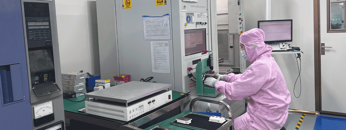
IPM modules operate under high voltage and high current conditions, which can damage the module or cause personal injury if handled improperly. Laboratories must follow these rules:
- Power-off operations: Always disconnect all power supplies before wiring, modifying, or servicing circuits.
- ESD protection: Wear an antistatic wrist strap and work on an ESD-safe bench. Internal IGBTs and driver ICs are sensitive to static discharge.
- Isolation and insulation: Ensure the test platform and terminals are properly insulated to prevent leakage or short circuits.
- Two-person rule: For high-risk procedures such as high-voltage startup or full-load testing, one person operates while another supervises.
1.2 Essential Equipment for IPM Testing
Typical laboratory testing requires the following equipment:
- Adjustable DC power supply for the main bus voltage
- Isolated DC power supplies for gate drivers (typically +15 V / −8 V or +15 V single supply)
- Appropriate loads, such as resistive, inductive, or PMSM motor loads
- Oscilloscope (≥2 channels, preferably 4+, bandwidth ≥100 MHz) with high-voltage differential probes
- Current probes for phase and bus current measurement
- Function generator for PWM control signals
- Digital multimeter and thermal camera/thermocouples for electrical and temperature monitoring
- Short-circuit protection components such as limiting resistors or inductors
1.3 Standard IPM Test Circuit Connections
Main Power Circuit
- Connect the DC power supply to the P and N terminals of the IPM.
- Place a 470–1000 µF electrolytic capacitor across the bus.
- Add a 1 µF CBB capacitor near the terminals to suppress voltage spikes.
- Connect the U, V, and W outputs to the test load.
Driver Control Circuit
- Connect driver GND to COM.
- Connect +15 V to Vx terminals and −8 V or GND to COM, depending on module design.
- Feed PWM signals from the function generator into the INx control inputs.
Protection and Monitoring Circuit
- Connect the FO (fault output) through a 4.7 kΩ pull-up resistor to +5 V or +3.3 V.
- Monitor the signal using an oscilloscope or multimeter to capture fault events.

2. IPM Static Testing
(Low-Risk Pre-Inspection Without High Bus Voltage)
At this stage, only the driver power supply is applied. The main bus voltage remains disconnected.
This step verifies basic conduction performance, logic control, and protection functions, helping identify defective modules before dynamic testing.
2.1 Conduction and Resistance Testing
Purpose:Verify whether the internal IGBTs and freewheeling diodes are functioning properly.
Method:Use a multimeter in diode mode.
Typical results:
- N → U/V/W: Forward voltage of 0.2–0.4 V indicates normal diode conduction.
- U/V/W → P: Forward conduction should also be observed.
- P → U/V/W (reverse): Should show open circuit (OL).
- Upper and lower bridge resistance: Should remain high resistance; low resistance suggests module damage.
2.2 Driver Circuit and Logic Verification
Purpose:Ensure PWM signals properly drive the switching devices and confirm correct logic timing.
Procedure:
- Power only the driver supply (+15 V and −8 V).
- Generate a 10 kHz PWM signal with adjustable duty cycle.
- Monitor the PWM input using one oscilloscope channel.
- Measure output phase voltage relative to N using a high-voltage differential probe.
- Confirm that phase voltage rises and falls correctly with the PWM signal.
- Test all six bridge arms to verify proper dead-time control.
2.3 Protection Function Testing
Protection verification is essential for IPM reliability testing.
Undervoltage Lockout (UVLO)
Gradually reduce the driver supply voltage.When Vcc drops below the threshold (typically ~12 V):
- The IPM should disable gate drive.
- The FO pin should output a fault signal.
Overcurrent and Short-Circuit Protection
- Connect a low-resistance load to simulate overcurrent.
- Apply a short PWM pulse.
- Monitor phase current and FO signal simultaneously.
If current exceeds the protection threshold, the IPM should turn off all IGBTs within microseconds and trigger a fault signal.
3. IPM Dynamic Testing
(High-Voltage Operation and Load Verification)
Dynamic testing evaluates switching performance, load capability, and thermal behavior.
Strict safety procedures must be followed.
3.1 No-Load or Light-Load Testing
Purpose:Verify switching behavior at low stress.
Procedure:
- Set the bus voltage to 50–100 V.
- Use a resistive load or run the motor at low speed.
- Observe phase voltage and current waveforms.
The signals should show fast transitions without significant overshoot, and motor current should appear as a smooth sinusoidal waveform.
3.2 Switching Performance Testing
(Double-Pulse Method)
The double-pulse test is the standard method for evaluating switching losses.
Measurements include:
- Collector-emitter voltage (Vce)
- Collector current (Ic)
- Gate-emitter voltage (Vge)
By integrating the instantaneous Vce × Ic, engineers can calculate:
- Turn-on energy (Eon)
- Turn-off energy (Eoff)
3.3 Thermal Testing
Purpose:Evaluate heat dissipation performance during long-term operation.
Run the IPM under rated voltage and current, then measure the case temperature using a thermal camera.
The case temperature Tc must remain below the maximum rating, typically ≤150 °C.
3.4 Full-Load Testing
Purpose:Verify stable operation under maximum rated conditions.
Gradually increase bus voltage and load current to rated values while monitoring:
- Switching waveforms
- Fault signals
- Module temperature
All parameters must remain within safe limits.
4. Key Recommendations for IPM Laboratory Testing
- Follow a gradual test sequence: static → dynamic, low voltage → high voltage, light load → full load.
- Use proper probes: standard probes must never measure high voltage directly.
- Check the datasheet carefully: driver voltage, dead time, and protection thresholds vary by model.
- Optimize wiring layout: keep test wires short and thick, and place bus capacitors close to the P/N terminals.
Conclusion
A structured laboratory testing process enables comprehensive evaluation of IPM conduction behavior, driver logic, protection functions, load capability, and thermal performance.
These tests provide accurate data for IPM selection, system debugging, and reliability verification in applications such as:
- Motor drives
- Inverters and frequency converters
- UPS systems
- Solar and energy storage systems
By following this standardized testing workflow, engineers can develop more reliable, efficient, and cost-effective power electronics systems.