

We have advertised this upgrade before — same package, same price, silicon carbide inside — and the honest reaction from most engineers is a healthy dose of skepticism: how can swapping the switch technology not change anything? Fair question. This article answers it from the inside out: what hybrid SiC actually replaces, what shifts electrically, and which verification steps a drop-in replacement still deserves.
The Hybrid Architecture, Physically
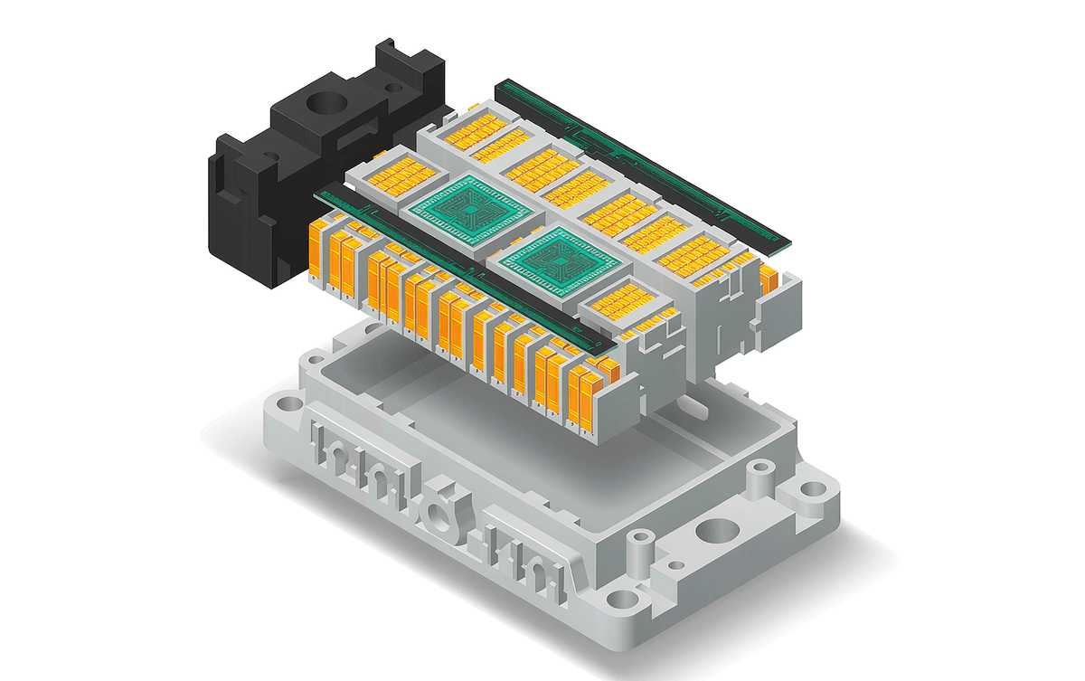
A hybrid SiC IPM is not an all-SiC module. The switching positions — where turn-on and turn-off losses live — are populated with SiC MOSFETs; the rest of the silicon (driver IC, protection logic, and in some topologies parts of the rectification path) stays. You keep the cost structure of silicon where silicon is good enough, and you buy SiC only where its near-zero reverse recovery and low switching energy pay rent. The module headline numbers follow: total loss down by roughly half in typical compressor-drive conditions, efficiency up 3–5 points, and junction temperature headroom extended toward 175 °C.
What Actually Changes Electrically
| Aspect | Silicon IGBT IPM | Hybrid SiC IPM | Do you need to act? |
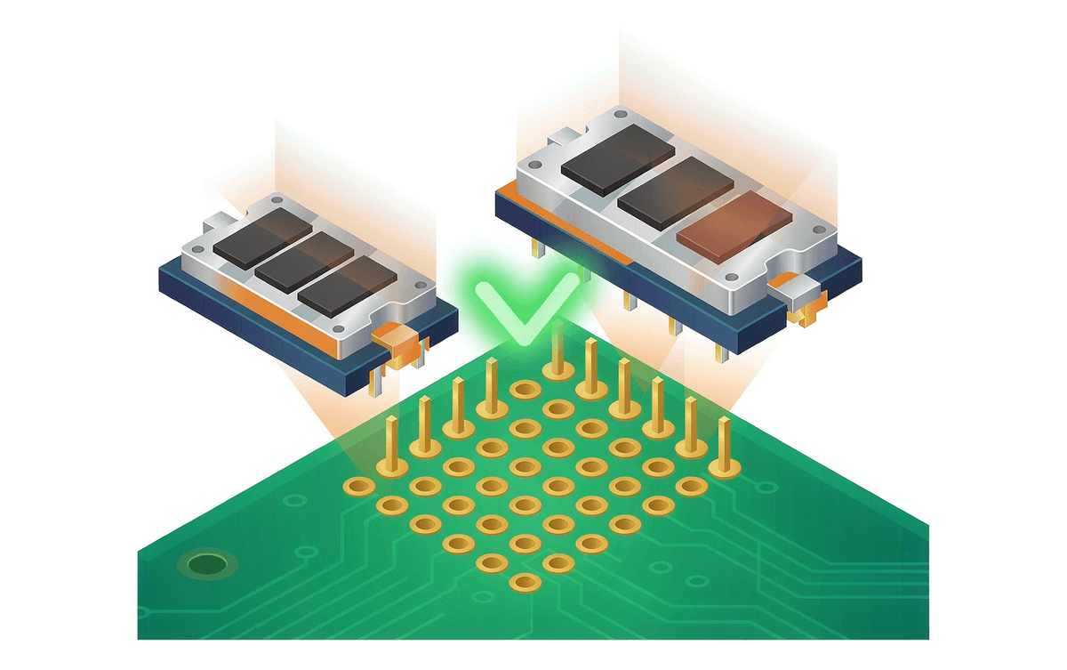
| Pinout / footprint | SIP/DIP standard | Identical pin map | No — PCB unchanged |
| Gate drive interface | Integrated driver | Integrated driver, matched to SiC | No — driver is inside the module |
| Switching speed / dv-dt | Moderate | Higher edge rates | Review layout, isolation and motor cable length |
| Protection thresholds | Tuned for IGBT | Re-tuned for SiC | No — but verify trip points during commissioning |
| Dead time requirement | Larger (tail current) | Smaller | Optionally reduce for more output range |
| Control software | PWM + protection logic | Same interfaces | No code change required |
Read that table as a boundary. Everything inside the module — the hard parts of a SiC adoption, like gate driving and protection scaling — has been absorbed by the module vendor. Everything outside — layout parasitics, dv/dt stress on insulation, EMC at the system level — stays your responsibility, and SiC's faster edges make those checks worth ten minutes of your time.
The Verification List for a Drop-In Swap
- Double-pulse first. Characterize switching energy and ringing on your actual bus and layout before running the line; we documented the method in our double-pulse test guide.
- Dead time sanity. The old IGBT-sized dead time still works, it is just conservative; if low-speed torque ripple matters to you, revisit dead time sizing.
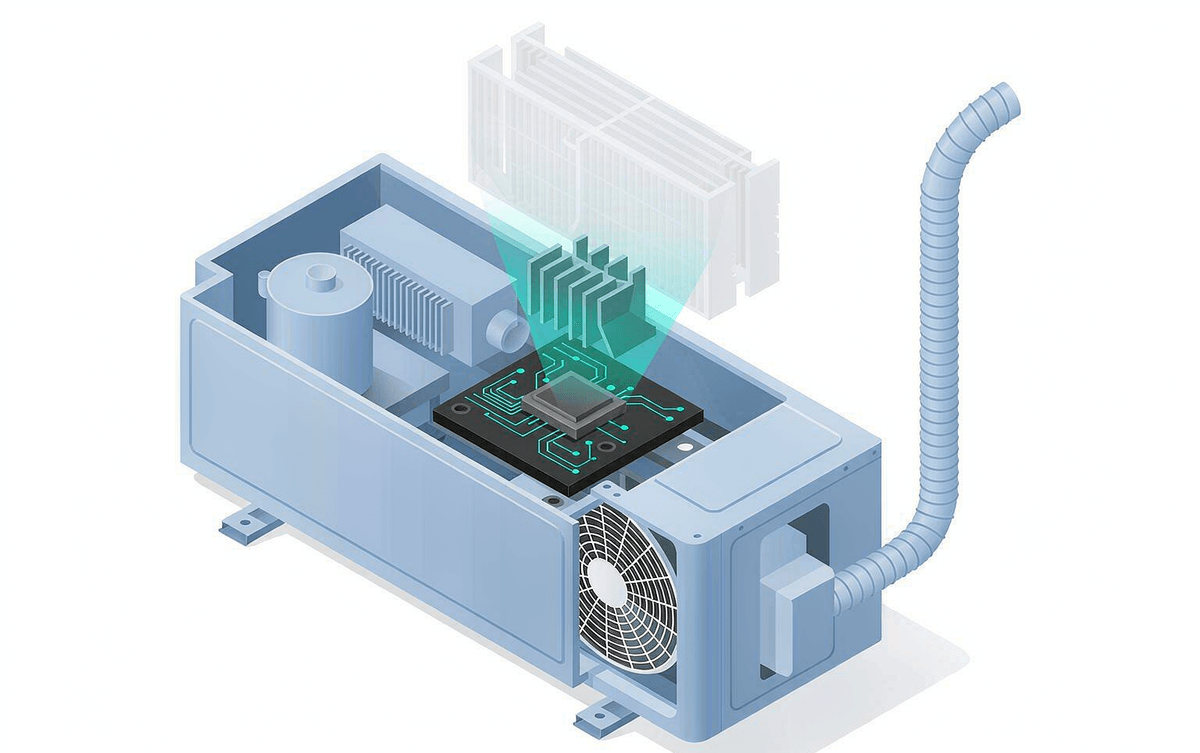
- Thermal re-check, downward. Lower loss means the same heatsink now runs cooler — an opportunity to shrink it or add margin; the heat path basics are in our thermal resistance guide.
- Protection trip points. Confirm over-current and short-circuit behavior at commissioning; the module handles it internally, but you should see it trip at least once on the bench.
Where the Upgrade Pays First
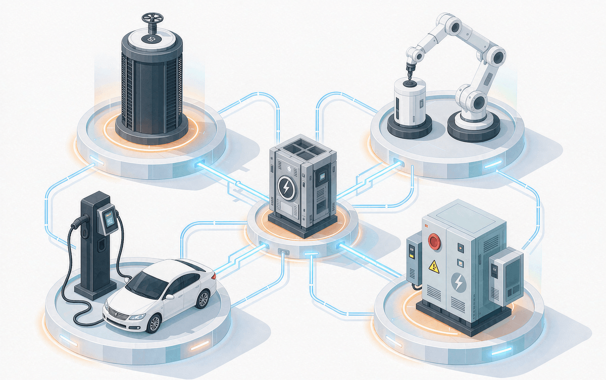
Compressor drives and heat pumps feel it immediately: higher APF with the same compressor, quieter operation because switching moves above the audible band, and a smaller heatsink or a sealed design with more margin. Servo drives gain torque ripple and density; solar and storage gain efficiency at partial load. The full product argument is in our SiC IPM upgrade announcement, and the integration-versus-discretes trade-off in IPM versus discrete.
Bottom line: a pin-to-pin SiC IPM upgrade changes the physics and keeps the interfaces. Treat it with the same bench respect as any new power stage — DPT, thermal check, one deliberate fault test — and it will behave exactly like the part it replaced, only cooler.
