

Swapping a 600 V / 15 A SIP IPM should be a ten-minute job: same package, same pinout, reflow and go. In practice it usually is — until the board comes back with a dead PFC stage or a bus-sense trace that goes nowhere. Three parts keep showing up in inverter appliance, fan and pump VFD, and servo auxiliary drive designs: the StarPower S1506C-1NMH, the S1506C-1RMH, and SHYSEMI's SYIM756C from our SIP35 family. They are pin-to-pin compatible, but the datasheets are not identical — and one pin in particular decides whether the swap is seamless. Here is the line-by-line diff.
Compatibility: One Footprint, One Hard Difference
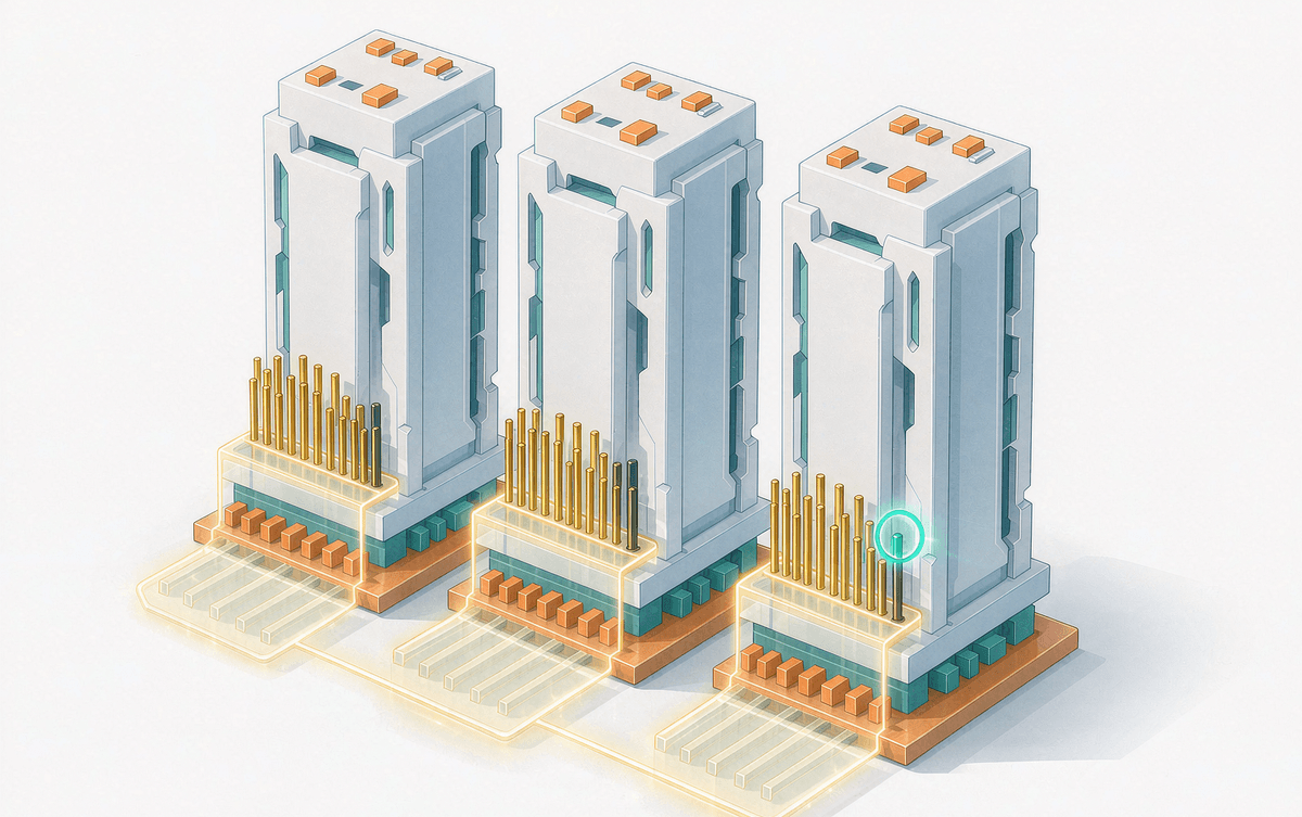
- The StarPower S1506C-1NMH and the S1506C-1RMH are electrically matched part for part — with a single hard exception: pin 17 exists on the S1506C-1RMH and is absent on the StarPower part.
- On the S1506C-1RMH, pin 17 (P2) duplicates pin 16 (P1): both are bus-voltage taps. P2 is simply an extra, separately routed sense line off the same DC bus.
- The SYIM756C implements the same internal circuit as the S1506C-1RMH, including both bus taps (VCC1/VCC2 on pins 16/17). In other words, one PCB footprint covers both sources.
That pin-17 detail sounds trivial until you meet it in layout: if your schematic samples the DC bus through P2/VCC2, a module without pin 17 leaves that net floating — the kind of fault that shows up as a nuisance trip at the customer, not at your bench.
Ratings: Identical on Paper
All three parts share the same headline ratings, so there is nothing to negotiate here:
| Parameter | Value (all three parts) |
| Inverter IGBT VCES | 600 V |
| Inverter rated / peak current IO / IPK | 15 A / 30 A |
| PFC rated / peak current | 30 A / 60 A |
| Bus voltage (DC / surge) | 450 V / 500 V |
| Isolation VISO | 2000 Vrms / 1 min |
| TJ / TC operating range | −40…+150 °C / −40…+125 °C |
Since the StarPower part tracks the S1506C-1RMH electrically, the rest of this comparison pairs the S1506C-1RMH against the SYIM756C — because that is where the real differences live.
Electrical and Thermal, Line by Line
| Parameter | S1506C-1RMH | SYIM756C |
| Inverter VCE(sat) @ 15 A | 1.7 V (max 2.3 V) | 1.7 V (max 2.1 V) |
| Inverter FRD VF @ 15 A | 1.9 V (max 2.5 V) | 1.6 V (max 2.2 V) |
| PFC VCE(sat) @ 30 A | 1.7 V (max 2.2 V) | 1.65 V (max 2.0 V) |
| PFC diode | Standard FRD, VF ≈ 2.0 V | SiC-SBD, VF ≈ 1.6 V |
| Inverter tON / tOFF | 0.8 / 0.9 µs | 0.84 / 1.42 µs |
| ITRIP threshold | 0.50 V | 0.50 V |
| Inverter Rth(j-c) | 4.7 °C/W | 3.7 °C/W |
| PFC max carrier frequency | 70 kHz | 100 kHz |
| Minimum dead time | 1.5 µs | 2 µs |
| VDD range | 13.5–16.5 V | 13.5–18 V |
| Built-in NTC (25 °C / B value) | 100 kΩ / 4250 K | 100 kΩ / 4250 K |
One note on reading the switching-time row: tON/tOFF in SIP IPM datasheets are module-level figures that include driver propagation delay, so they run an order of magnitude slower than bare-die numbers. The SYIM756C's longer turn-off (1.42 µs) is a consequence of its protection-rich driver design; it only matters if your dead-time budget is already tight — which the checklist below covers.
Where the Differences Actually Matter
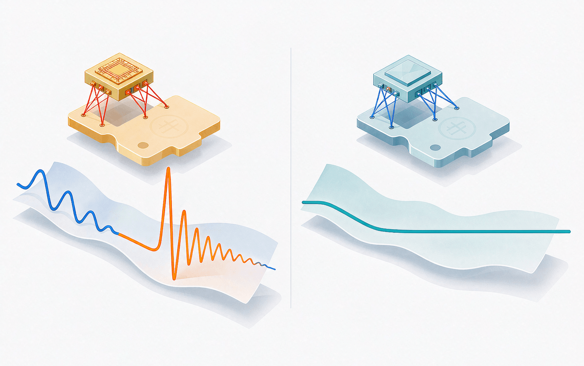
1. The PFC diode is the biggest divider. The SYIM756C puts a SiC Schottky barrier diode in the PFC stage where the S1506C-1RMH runs a standard FRD. Reverse recovery current drops to nearly zero: PFC-stage efficiency rises, EMI softens, and the carrier can be pushed to 100 kHz versus 70 kHz — headroom that suits high-power-factor designs with small boost inductors. If you are weighing silicon versus SiC at the 600 V class more broadly, our 600–650 V device comparison maps the whole field; and for what the missing reverse-recovery spike means bench-side, see how SiC Schottky diodes reshape boost PFC.
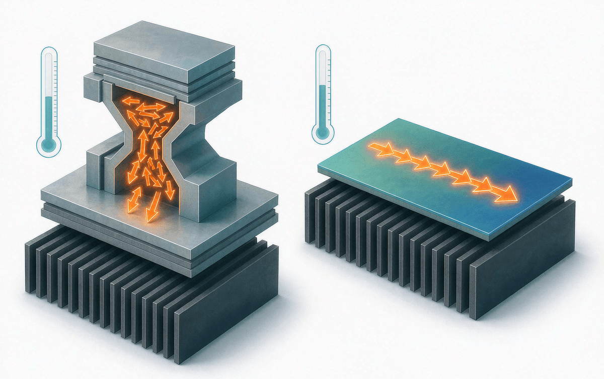
2. Thermal path. The SYIM756C uses an insulated metal substrate (IMS): inverter-stage Rth(j-c) is 3.7 °C/W against the S1506C-1RMH's 4.7 °C/W — about 21% lower. At the same load that is a cooler case temperature and more thermal margin over life, which is worth more than it sounds in sealed appliance enclosures. The Rth budget math is worked through in our thermal resistance guide.
3. Pin 17, again. If the board samples the bus (P2/VCC2), the replacement must carry pin 17 — the S1506C-1RMH and SYIM756C both qualify; the StarPower part does not. This is the single most common rework item we see when customers cross-reference these parts.
4. Everything else lines up. Drive thresholds, UVLO reset behavior, ITRIP, and the built-in NTC characteristic are essentially aligned across all three, so re-engineering concentrates on two areas: bus sampling and PFC timing. And because the PFC switch edges get faster with SiC, it pays to re-check your gate resistor and dv/dt — EMI suppression practice for IPMs carries over directly.
Before It Goes on the Board
- Confirm whether pin 17 (bus voltage, P2/VCC2) has a net on your PCB — this decides the part family, not preference.
- Keep dead time ≥ 2 µs to avoid shoot-through on the inverter leg.
- Re-verify PFC gate resistance and dv/dt with the SiC-SBD's faster recovery in mind.
- Check the NTC scaling in firmware against the 100 kΩ / 4250 K characteristic — it is shared across all three, but only if your ADC math assumed it.
- If the footprint was laid out for a 17-pin part, do not assume a 16-pin drop-in is "compatible enough" — an unconnected bus-sense net will fail late.
Bottom Line
All three parts are same-spec, same-package and pin-to-pin swappable — the question is never whether they interchange, but what each swap costs or returns you: the PFC device (SiC or not), thermal resistance, carrier-frequency ceiling, and pin 17. If your design wants an efficient, low-EMI PFC stage, a cooler case at the same load, and compatibility with boards that sample the bus through pin 17, the SYIM756C is the second source worth shortlisting. As the module maker we can also support the selection directly — bring the bus-sense schematic and PFC timing sheet, and we will review the swap with you.
