

When a power stage fails in the field, the autopsy almost always shows the same ending: a burned module. But "it got too hot" is a symptom, not a mechanism. The mechanism is thermal runaway — an electro-thermal positive feedback loop where a small temperature rise degrades device parameters, which increases losses, which raises temperature further. Once the loop closes, no heatsink can catch it. This article walks through the physics, the four stages, the three root causes, and a prevention checklist you can apply at design time.
What Thermal Runaway Actually Is
Silicon MOSFETs and IGBTs have positive temperature coefficients in the wrong places: on-resistance and leakage current both climb with junction temperature. Total dissipation is roughly conduction loss (I² × R, rising with T) plus switching loss (rising with slower transitions at high temperature). Under normal conditions heat generated ≤ heat removed, so temperature settles. If cooling degrades or load rises, temperature creeps up → parameters worsen → losses rise → temperature climbs faster. That is the loop, and it ends with the junction exceeding its limit — 150–175 °C for silicon, around 200 °C for SiC — with die destruction, solder layer melt-down or package rupture.
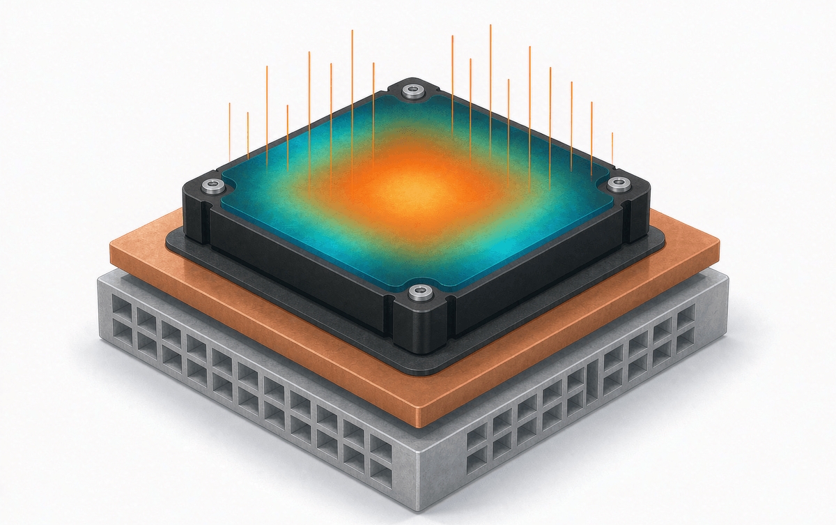
The Four Stages of a Runaway Event
| Stage | Condition | What you would see | Recoverable? |
| 1. Initial temperature rise | Heat generated ≤ heat removed | Overload, aged thermal grease, fouled fan; mild temperature drift | Yes — routine intervention |
| 2. Loss escalation | Heat generation starts winning | RDS(on)/leakage rising, losses climbing at the same load | Yes — reduce load, restore cooling |
| 3. Positive feedback | Heat generation ≫ heat removal | Exponential temperature rise, protection tripping or absent | No — damage accumulating |
| 4. Device destruction | Junction beyond limit | Die breakdown, solder melt, package rupture, system shutdown | No — failure is final |
The practical takeaway from the table: everything you do must keep the system in stage 1, or push it back from stage 2. Stage 3 is already a write-off in progress.
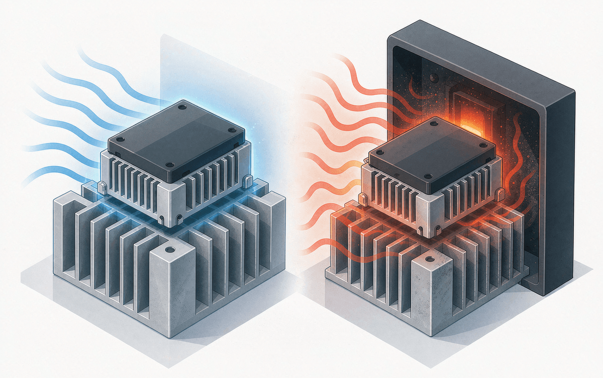
Three Root Causes We See Most Often
- Cooling hardware defects — undersized heatsinks, cracked or dried thermal grease, poor module-to-heatsink contact, blocked ducts, failed fans. All of them raise thermal resistance, which is the trigger condition.
- Operating and circuit design issues — continuous overload, switching frequency set too high, uneven current sharing between parallel devices, or a gate drive that leaves the device partially on.
- Aging and environment — leakage current creeping up over years of service, sealed enclosures with no ventilation plan, dust and high ambient temperature compounding each other.
Layered Prevention: From Heatsink to Control Loop
Layer 1 — passive cooling, done honestly. Size the heatsink from the worst-case loss, not the typical loss. Keep the chip-to-heatsink path intact: fresh thermal interface material, flat mounting, even screw torque, clean ducts. If you want the numbers behind this, our walkthrough of IGBT thermal resistance parameters shows how each interface adds up.
Layer 2 — active temperature control. Monitor junction temperature with the module's NTC and act on it: derate switching frequency or output current at a warning threshold, and shut down hard at the critical threshold. Getting reliable readings is its own skill — see our guide on NTC temperature sensor measurement, and for the protection side, how IPM thermal shutdown works.
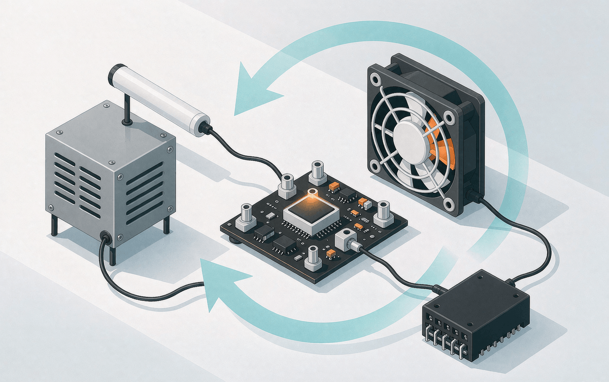
Layer 3 — circuit design margins. In parallel arrays, design for even sharing — layout symmetry and parameter matching — because a single device hogging current becomes a local hot spot that spreads. Our note on static, dynamic and thermal effects in parallel IGBTs covers the details. Keep gate drive voltage stable so devices never linger in the linear region, and derate current, voltage and temperature by 30–50% for long service life.
Layer 4 — device selection. For high-frequency, high-power designs, SiC devices attack the root cause: far lower conduction and switching losses, higher temperature headroom. That is exactly why many platforms are moving to hybrid SiC IPMs instead of adding more heatsink.
The One-Paragraph Summary
Thermal runaway is not "too hot" — it is a feedback loop where heat degrades parameters, parameters raise heat. It is irreversible once the loop closes, so prevention must come before it: derated selection first, then honest thermal design, then current sharing, then active protection, then material upgrades. Check our overview of IPM failure modes if you are troubleshooting a specific failure, and keep the maintenance routine boring: inspect thermal interfaces, fans and ducts on a schedule.
