

Every power electronics project eventually runs into the same two jobs: turning AC into DC, and turning DC back into AC. An EV onboard charger rectifies grid AC to charge the battery; the traction inverter then turns battery DC back into AC to spin the motor. A variable-frequency air conditioner does both in one box. The difference between AC and DC has been covered before — in this article we focus on the conversion itself and, more importantly, on which power devices do the work and what they cost you in efficiency.
Rectification (AC to DC) and Inversion (DC to AC) in One Look
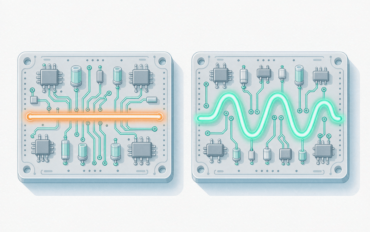
Rectification converts line-frequency or high-frequency AC into DC by forcing current to flow in one direction. Inversion does the opposite: it chops a DC bus into a controlled AC output using fast semiconductor switches, usually shaped by PWM. One direction cares mostly about forward drop and reverse recovery; the other cares mostly about switching loss and safe turn-off. That single sentence drives most of the device selection you will ever do on the two sides of a converter.
The Rectifier Path: From Diode Bridges to Synchronous Rectification
The classic front end is a diode bridge — four or six diodes steering current so the output polarity never flips. It is cheap, rugged and nearly lossless at light load, but every diode drop (typically 0.7–1.5 V) burns power at high current. In low-voltage, high-current outputs, engineers move to synchronous rectification with MOSFETs. And when the bridge runs behind a high-frequency stage, the diodes must recover fast: a slow diode with large reverse recovery charge dumps loss into every switching cycle. That is why the nine key FRD parameters matter as much in the rectifier path as the diode's forward drop does.
One practical detail that is often missed: in inductive circuits the diode is also the freewheeling path that keeps current flowing when the switch turns off. Choosing the right freewheeling diode protects the main switch and keeps ringing under control.
The Inverter Path: Three-Phase Bridges, PWM and Dead Time
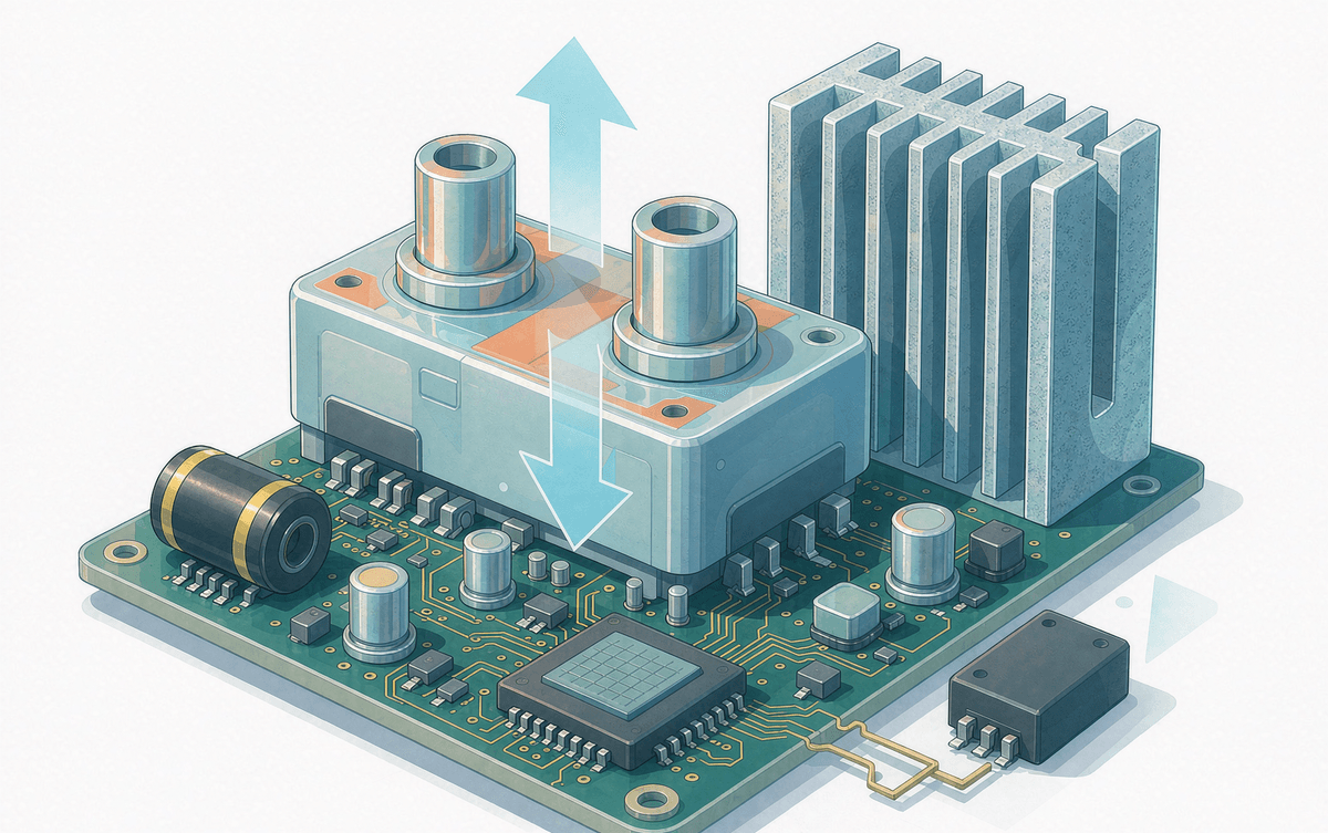
On the DC-to-AC side, the workhorse is the three-phase full bridge built from six IGBTs or SiC MOSFETs (or an IPM that integrates them with drivers and protection). The modulator switches each pair thousands of times a second, so switching energy — not conduction drop — often dominates. Topology matters too: many designs start from half-bridges before scaling up, and it pays to be clear on half-bridge versus three-phase full-bridge trade-offs before locking the layout.
Dead time is the inverter's necessary evil: a small window when both switches in a leg are off, preventing shoot-through at the cost of output distortion. If your drive is misbehaving at low speed or light load, reviewing dead time causes and fixes is the first thing we recommend.
Where the Losses Come From — and How to Trade Them
Rectifier side: forward drop, reverse recovery, and snubber loss. Inverter side: conduction loss (VCE(sat) or RDS(on)), switching energy Eon/Eoff, and gate drive loss. SiC shifts the balance — near-zero reverse recovery and much lower switching energy at high frequency, which is why many motor-drive platforms are upgrading from silicon IGBT to hybrid SiC IPMs without redesigning the board.
| Item | Rectifier (AC to DC) | Inverter (DC to AC) |
| Core job | Force one-way current flow | Shape DC bus into PWM AC output |
| Key devices | Diodes, FRDs, SR MOSFETs | IGBTs, SiC MOSFETs, IPMs |
| Dominant loss | Forward drop, reverse recovery | Switching energy, conduction drop |
| Typical circuits | Diode bridge, PFC front end | Three-phase full bridge, LLC |
| Key selection specs | VF, Qrr, softness, surge rating | VCE(sat)/RDS(on), Eon/Eoff, short-circuit rating |
| Typical applications | OBC, auxiliary supplies, DC bus | Motor drives, PV inverters, PCS |
Selection Advice: Design Both Ends of the Chain Together
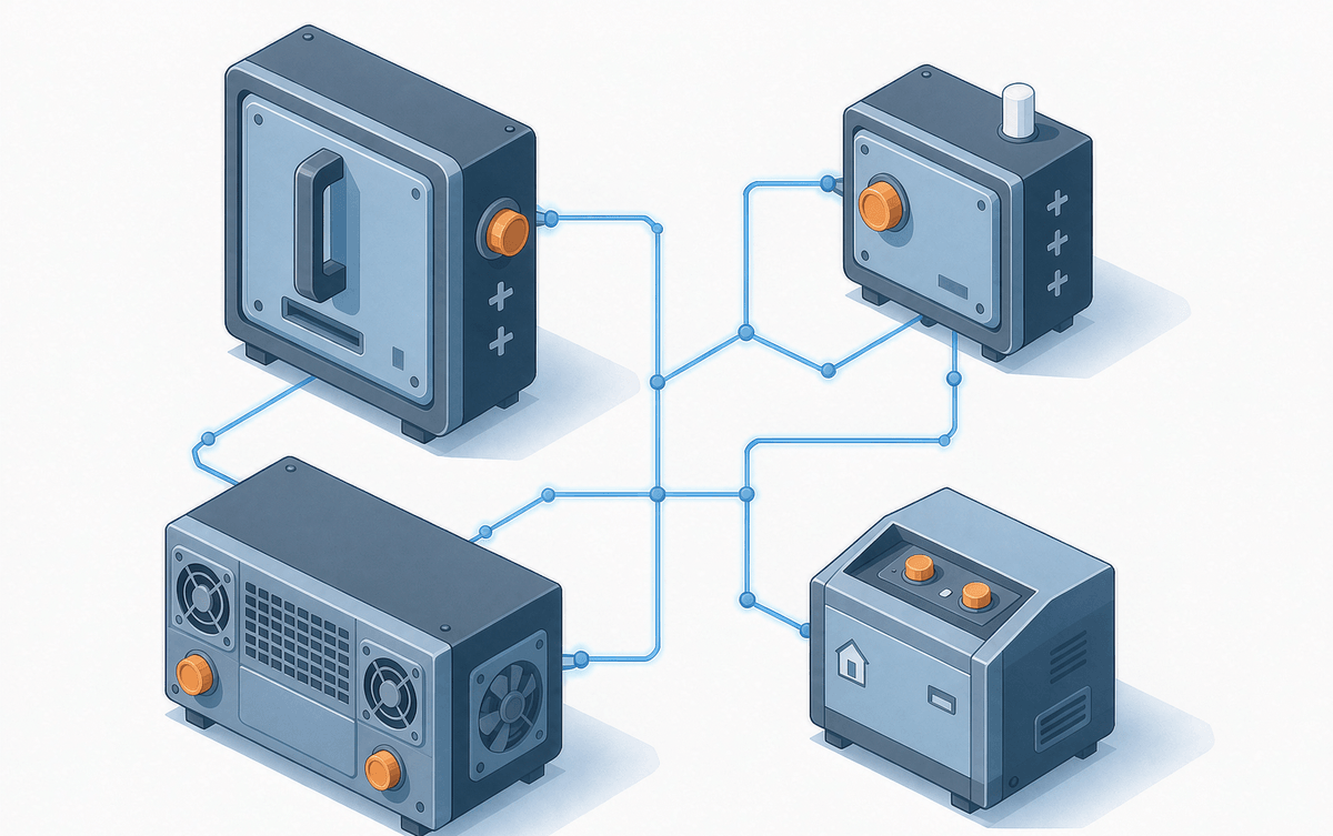
A converter is only as good as its weakest stage. If the rectifier runs cool but the inverter runs hot, the heatsink is sized by the wrong stage. We suggest picking the inverter switch first (voltage class, current, switching frequency), then matching the rectifier and freewheeling diodes to the same thermal budget. For motor-drive builders weighing integration against flexibility, our comparison of IPM versus discrete IGBT solutions covers the total-cost angle in detail.
SHYSEMI supplies both sides of the conversion chain — FRDs, IGBT modules, SiC MOSFETs and integrated IPMs — so the two stages can be matched instead of compromised. If you are debugging a conversion stage right now, the application notes linked above are the fastest starting point.
