

Most bad IGBT choices in solar inverters are not made in the datasheet — they are made before the datasheet is even opened, by starting from a part number instead of the system. A 3 kW rooftop string inverter and a 1 MW central station share the same selection logic, just at different scales: the DC bus sets the voltage class, the hottest operating hour sets the current, and the topology sets how much stress each switch actually sees. This article walks that chain the way our FAEs do on a real project — and closes with the four mistakes we keep meeting in the field. The full product side is covered in our PV inverter IGBT overview.
Let the DC Bus Pick the Voltage Class
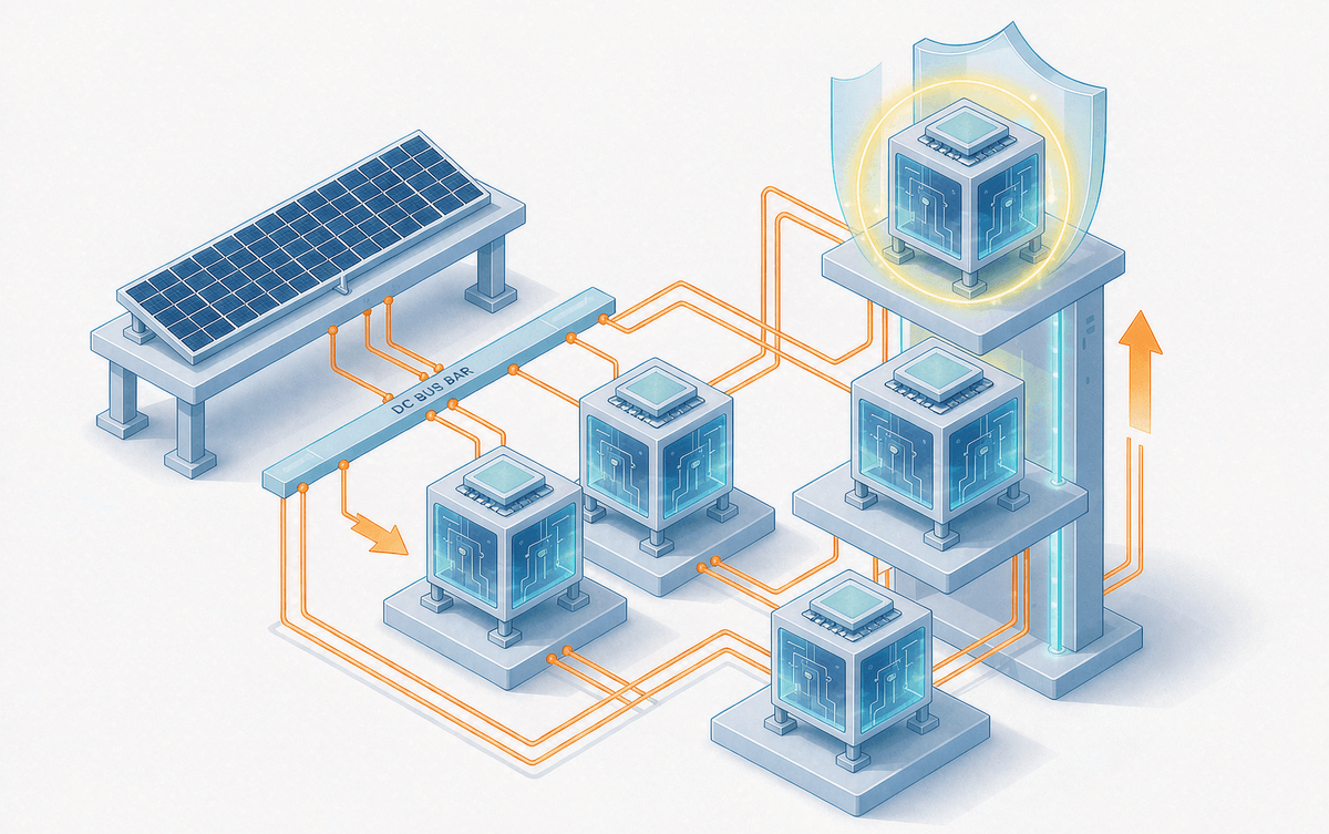
Residential and commercial inverters run 600–1000 V DC buses and are served by 1200 V class devices; utility-scale 1500 V buses need 1700 V class. The margin is not decorative: on top of the nominal bus sit switching overshoots (a function of layout stray inductance and turn-off speed), MPPT excursions above nominal string voltage, and grid-side transients. Underrating the class saves a little on the BOM and buys a fuse-like failure mode — die breakdown on the first cloudy-to-sunny string swing. Overshoot on a real layout is easy to measure with a double-pulse rig before committing the design; we described the setup in our double-pulse guide.
Size the Current for the Hottest Hour, Not the Nameplate
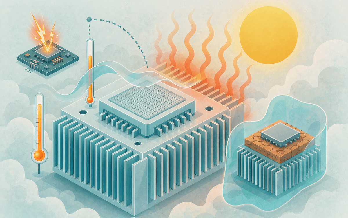
Datasheet current is measured at 25 °C; your inverter delivers its annual peak at a 60 °C roof or container. What actually limits output is the junction temperature budget, and the chain runs: conduction loss (∝ VCE(sat), typically 1.5–2.0 V on Trench FS generations) + switching loss (∝ Eon/Eoff, what matters at 20–40 kHz) → thermal resistance Rth(j-c) (≤0.3 °C/W is the working bar for mid-power) → coolant or ambient. A module rated 175 °C Tj,max holds full output through a summer afternoon where a 150 °C part derates 30% — and derated inverters do not generate revenue. The arithmetic of that chain is laid out in our thermal resistance parameter guide.
The Four Mistakes We See Most
- Buying the voltage class too close. Nominal bus plus a dash of optimism, no allowance for overshoot or string transients — the module survives commissioning and dies in month eight.
- Optimizing unit price over junction temperature. The cheap 150 °C part derates exactly when the plant is making its yearly peak; the lost kWh cost more than the premium over and over.
- Under-specifying the heat path. Rth budgeted on typical, not worst-case, ambient — sustained overtemperature ages solder and bond wires fast enough to halve life; the aging mechanisms are the same ones we catalog in our failure-mode overview.
- Ignoring short-circuit withstand. Grid faults and load steps are a when, not an if; 10 μs withstand plus desat detection and soft turn-off is the minimum defensible spec.
At 1500 V, the Topology Changes the Math
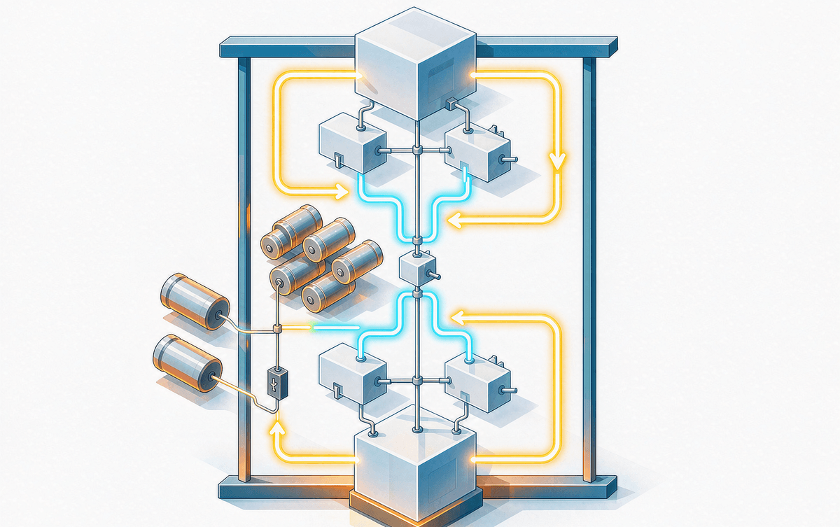
Once the bus moves to 1500 V, most serious designs move to a three-level (NPC/T-type) stage, and the IGBT question changes shape: each device now blocks roughly half the bus, so 1700 V class devices run with real margin, switching loss drops, and filter size follows. Fewer, bigger modules beat paralleling small ones — current sharing, oscillation and thermal mismatch are the price of parallel discrete, as we detailed in the paralleling effects guide. A single 1700 V module in HPD packaging with double-sided cooling can carry a 200 kW+ output stage on its own; our low-stray package layout (below ~15 nH) keeps the overshoot from eating the margin you just bought — the EMI side of that trade is in our EMI suppression notes.
Lifetime and Payback, Without the Marketing
Two numbers decide the 20-year conversation. First, power-cycling capability: ≥50 k cycles is the entry bar for a PV design life, and silver-sintered, copper-bonded parts (our F-series) are specified beyond 100 k — roughly double a standard wire-bonded build. Second, efficiency payback: on a 10 kW commercial inverter, 1–2 points of conversion efficiency is worth 800–1600 kWh a year, which at typical tariffs returns a module premium in about three years — after that it is pure yield. And when the efficiency ceiling itself becomes the constraint, that is where SiC enters; the economics are quantified in how SiC is changing solar inverter economics. For a starting point at 1200 V / 200 A-class, the SYMT200HF120T2VH-M module page carries the full ratings.
Selection done in this order — bus voltage, hottest-hour current, topology, then lifetime — rarely gets redesigned. Done backwards, it almost always does. If you want a second pair of eyes on a bus in design, send us the string configuration and enclosure environment; the loss-and-thermal model behind this article is the same one our FAEs run.
